Subaru Legacy III (2000-2003 year). Manual - part 510
EN(H4DOSTC)-210
ENGINE (DIAGNOSTICS)
DIAGNOSTIC PROCEDURE WITH DIAGNOSTIC TROUBLE CODE (DTC)
BB:DTC P1239 — EXHAUST CONTROL VALVE SOLENOID CIRCUIT LOW
(NEGATIVE PRESSURE) —
• TROUBLE SYMPTOM:
• Poor driving performance
CAUTION:
After repair or replacement of faulty parts, conduct Clear Memory Mode <Ref. to EN(H4DOSTC)-35,
OPERATION, Clear Memory Mode.> and Inspection Mode <Ref. to EN(H4DOSTC)-33, Inspection
Mode.> .
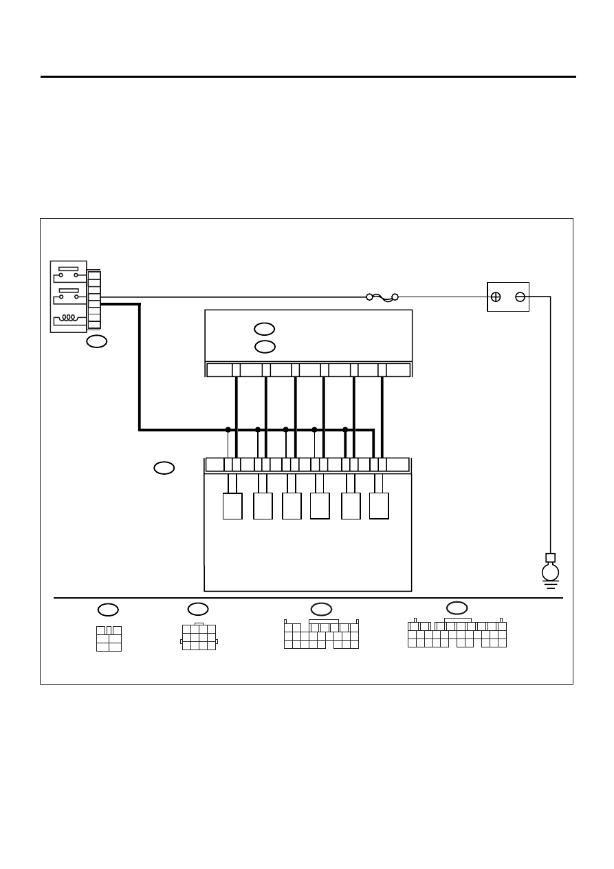
• WIRING DIAGRAM:
EN-00939
B220
B47
E
BATTERY
MAIN RELAY
3
B136
ECM
SBF-5
5
2
1
4
6
B47
3
4
1
2
5
6
B220
SOLENOID
BOX ASSY
1
2
3
4
5
6
7
8
9
10
11
12
(A)
(B)
(C)
(D)
(E)
(F)
(A): RELIEF VALVE SOLENOID 2
(B): RELIEF VALVE SOLENOID 1
(C): EXHAUST VALVE CONTROL SOLENOID VALVE
(NEGATIVE PRESSURE)
(D): EXHAUST VALVE CONTROL SOLENOID VALVE
(POSITIVE PRESSURE)
(E): INTAKE AIR CONTROL SOLENOID VALVE
(F): EXHAUST VALVE CONTROL DUTY SOLENOID VALVE
C:
B137
D:
C11
C12
C3
C1
D22
D11
1 2 3 4
5 6 7 8
9 10 11 12
B136
1 2
7
8 9
5
6
3
4
10 11 12
19 20 21
13 14 15 16
17 18
22 23 24
B137
1
2
7
8
9
5
6
3
4
10 11 12
19 20 21
29 30 31
13 14 15 16 17
27 28
18
22 23 24 25 26