Subaru Legacy III (2000-2003 year). Manual - part 462
EN(H4DOSTC)-18
ENGINE (DIAGNOSTICS)
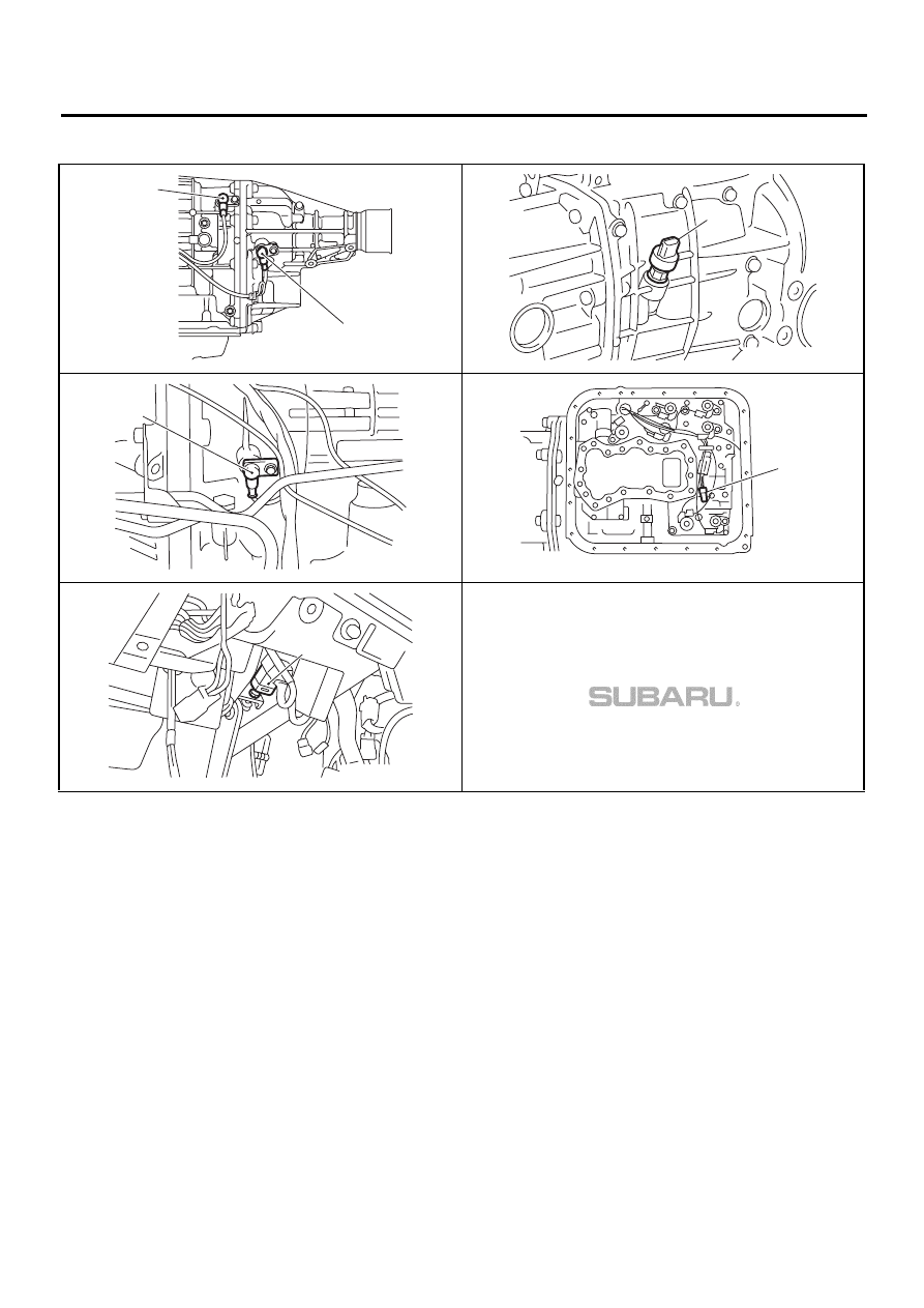
ELECTRICAL COMPONENTS LOCATION
• SENSOR
(1) Rear vehicle speed sensor (for AT vehicles)
(2) Front vehicle speed sensor (for MT vehicles)
(3) Front vehicle speed sensor (for AT vehicles)
(4) Torque converter turbine speed sensor
(5) ATF temperature sensor (for AT vehicles)
(6) Brake light switch
EN-00881
( 1 )
( 3 )
EN-00882
( 2 )
EN-00883
( 4 )
EN-00884
( 5 )
EN-00885
( 6 )