Subaru Legacy III (2000-2003 year). Manual - part 438
CO(H4DOSTC)-6
COOLING
GENERAL DESCRIPTION
D: PREPARATION TOOL
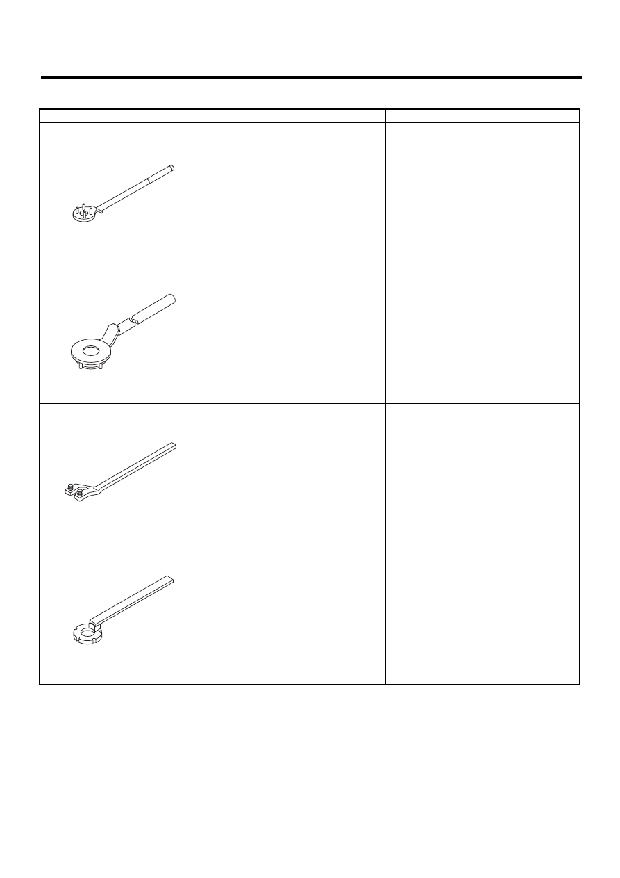
ILLUSTRATION
TOOL NUMBER
DESCRIPTION
REMARKS
499977100 (MT
model)
CRANK PULLEY
WRENCH
Used for fixing crankshaft pulley when loos-
ening and tightening crankshaft pulley bolts.
499977400 (AT
model)
CRANK PULLEY
WRENCH
Used for fixing crankshaft pulley when loos-
ening and tightening crankshaft pulley bolts.
18231AA010
CAMSHAFT
SPROCKET
WRENCH
• Used for removing and installing camshaft
sprocket. (Intake side)
• Camshaft sprocket wrench (499207100) is
also available.
499207400
CAMSHAFT
SPROCKET
WRENCH
Used for removing and installing camshaft
sprocket. (Exhaust side)
ST-499977100
ST-499977400
ST18231AA010
ST-499207400