Subaru Legacy III (2000-2003 year). Manual - part 297
SC(H6DO)-12
STARTING/CHARGING SYSTEMS
STARTER
6. SWITCH ASSEMBLY OPERATION
1) Connect the terminal S of switch assembly to
positive terminal of battery with a lead wire, and
starter body to ground terminal of battery. The pin-
ion should be forced endwise on shaft.
CAUTION:
With the pinion forced endwise on shaft, starter
motor can sometimes rotate because current
flows, through pull-in coil, to motor. This is not
a problem.
2) Disconnect the connector from terminal M, and
then connect the positive terminal of battery and
terminal M using a lead wire and ground terminal to
starter body.
In this test set up, the pinion should return to its
original position even when it is pulled out with a
screwdriver.
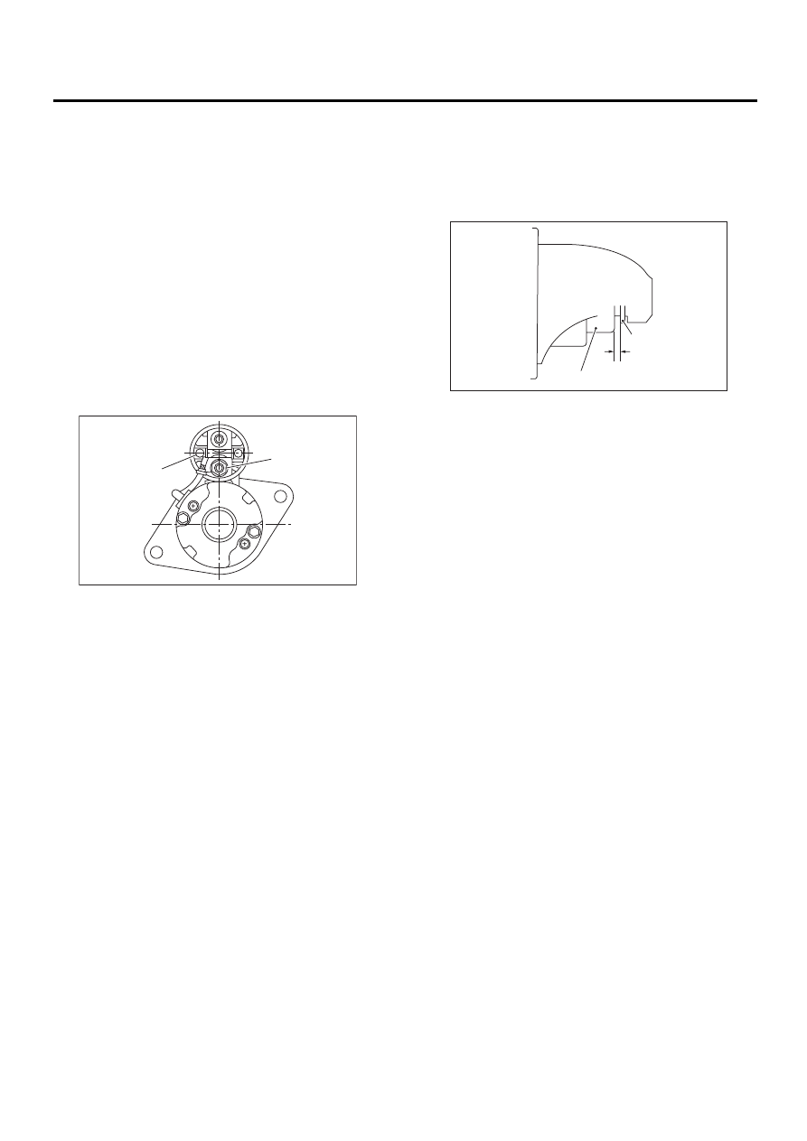
7. PINION GAP
1) Measure pinion gap while the pinion is pulled out
as shown in the figure.
Pinion gap:
0.5 — 2.0 mm (0.020 — 0.079 in)
If the motor is running with the pinion forced end-
wise on shaft, disconnect the connector from termi-
nal M of switch assembly, and then connect
terminal M to ground terminal (
−
) of battery with a
lead wire. Next, gently push the pinion back with
your fingertips, and then measure the pinion gap.
2) If the pinion gap is outside specified range, re-
move or add number of adjustment washers used
on the mounting surface of switch assembly until
correct pinion gap is obtained.
(A) Terminal S
(B) Terminal M
SC-00160
( A )
( B )
(A) Pinion
(B) Gap
(C) Stopper
SC-00027
( A )
( B )
( C )