Subaru Legacy III (2000-2003 year). Manual - part 23


  Index      Subaru     Subaru Legacy III - service repair manual 2000-2003 year


Search            


Content   ..  21  22  23  24   ..


Subaru Legacy III (2000-2003 year). Manual - part 23


PM-42

PERIODIC MAINTENANCE SERVICES

TIRE ROTATION

26.Tire Rotation

A: INSPECTION

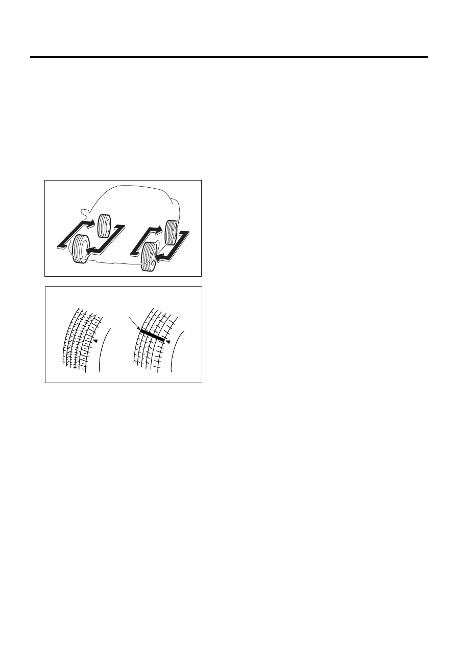
1) Replace the tire if the tread depth is less than 1.6
mm (0.063 in) or if wear indicators appear across
the tire tread. (It is recommended that both right
and left tires are replaced as a set.)
2) Adjust the wheel alignment if abnormally uneven
tire wear is found.
3) Also, rotate the tires between the front and rear
tires as illustrated, in order to ensure uniform tire
wear.

(A) New tread

(B) Worn tread

(C) Tread wear indicator

PM-00079

PM-00080

(A)

(B)

(C)

PM-43

PERIODIC MAINTENANCE SERVICES

STEERING SYSTEM (POWER STEERING)

27.Steering System (Power 

Steering)

A: INSPECTION

1. STEERING WHEEL

1) Set steering wheel in a straight-ahead position,
and check wheel spokes to make sure they are cor-
rectly set in their specified positions. 
2) Lightly turn steering wheel to the left and right to
determine the point where front wheels start to
move.
Measure the distance of the movement of steering
wheel at the outer periphery of wheel. 

Steering wheel free play:

0 — 17 mm (0 — 0.67 in)

Move steering wheel vertically toward the shaft to
ascertain if there is play in the direction.

Maximum permissible play:

0.5 mm (0.020 in)

3) Drive vehicle and check the following items dur-
ing operation.

(1) Steering force ..............
The effort required for steering should be
smooth and even at all points, and should not
vary.
(2) Pull to one side ............
Steering wheel should not be pulled to either
side while driving on a level surface.
(3) Wheel runout ................
Steering wheel should not show any sign of
runout.
(4) Return factor ...............
Steering wheel should return to its original posi-
tion after it has been turned and then released.

2. STEERING SHAFT JOINT

1) When steering wheel free play is excessive, dis-
connect universal joint of steering shaft and check
it for any play and yawing torque (at the point of the
crossing direction). Also inspect for any damage to
sealing or worn serrations. If the joint is loose, re-
tighten the mounting bolts to the specified torque.

Tightening torque:

24 N·m (2.4 kgf-m, 17.4 ft-lb)

3. GEARBOX

1) With wheels placed on a level surface, turn
steering wheel 90

°

 in both the left and right direc-

tions.
While wheel is being rotated, reach under vehicle
and check for looseness in gearbox. 

Tightening torque:

59 N·m (6.0 kgf-m, 43.4 ft-lb)

2) Check boot for damage, cracks or deterioration.
3) With vehicle on a level surface, quickly turn
steering wheel to the left and right.
While steering wheel is being rotated, check the
gear backlash. If any unusual noise is noticed, ad-
just the gear backlash in the following manner. 

(1) Tighten adjusting screw to 7.4 N·m (0.75
kgf-m, 5.4 ft-lb) and then loosen. Repeat this op-
eration twice.
(2) Retighten adjusting screw to 7.4 N·m (0.75
kgf-m, 5.4 ft-lb) and back off 25

°

(A) Free play

PM-00065

(A)

S U B A R U

S R S

A I R B A G

(A) Boot

(B) Gearbox mounting bolts

PM-00066

PM-00067

(A)

(B)

PM-44

PERIODIC MAINTENANCE SERVICES

STEERING SYSTEM (POWER STEERING)

(3) Apply liquid packing to at least 1/3 of entire
perimeter of adjusting screw thread.

(4) Install lock nut. While holding adjusting
screw with a wrench, tighten lock nut using ST.

ST

926230000

SPANNER

Tightening torque (Lock nut):

39 N·m (4.0 kgf-m, 29 ft-lb)

Hold the adjusting screw with a wrench to pre-
vent it from turning while tightening the lock nut.

4. TIE-ROD

1) Check tie-rod and tie-rod ends for bends,
scratches or other damage.

2) Check connections of knuckle ball joints for play,
inspect for damage on dust seals, and check free
play of ball studs. If castle nut is loose, retighten it
to the specified torque, then tighten further up to
60

°

 until cotter pin hole is aligned.

Tightening torque:

27 N·m (2.75 kgf-m, 19.9 ft-lb)

3) Check lock nut on the tie-rod end for tightness. If
it is loose, retighten it to the specified torque.

Tightening torque:

83 N·m (8.5 kgf-m, 61.5 ft-lb)

5. POWER STEERING FLUID LEVEL

1) Place vehicle with engine “off” on the flat and
level surface.
2) Inspect fluid level by indicator of reservoir tank.
If the level is at lower point or below, add fluid to
keep the level in the specified range of the indica-
tor. If at upper point or above, drain fluid by using a
syringe or the like.

(1) Check at temperature 20

°

C (68

°

F) on reser-

voir surface of oil pump; read the fluid level on
the “COLD” side.
(2) Check at temperature 80

°

C (176

°

F) on res-

ervoir surface of oil pump; read the fluid level on
the “HOT” side.

3) Bleed air when the following cases occur with
engine running or stopped:

(1) When fluid level varies 3 mm (0.12 in) or
more.
(2) When foam is produced on the fluid surface.
(3) When oil pump produces squeaky noise.

6. POWER STEERING FLUID FOR LEAKS

Inspect the underside of oil pump and gearbox for
power steering system, hoses, piping and their
couplings for fluid leaks.
If fluid leaks are found, correct them by retightening
their fitting bolts (or nuts) and/or replacing their
parts.

NOTE:
• Wipe the leakage fluid off after correcting fluid
leaks, or a wrong diagnosis is taken later.
• Also pay attention to clearances between hoses
(or pipings) and other parts when inspecting fluid
leaks.

(A) Apply liquid packing to at least 1/3 of entire 

perimeter.

(A) Tie-rod end

(B) Knuckle arm

PM-00068

(A)

PM-00069

(A)

(B)

HOT MAX.COLD MAX.

HOT MIN.

COLD MIN.

PS-00159

PM-45

PERIODIC MAINTENANCE SERVICES

STEERING SYSTEM (POWER STEERING)

7. HOSES OF OIL PUMP FOR DAMAGES

Check pressure hose and return hose of oil pump
for crack, swell or damage. Replace hose with a
new one if necessary.

NOTE:
Prevent hoses from revolving and/or turning when
installing hoses.

8. POWER STEERING PIPES FOR DAM-
AGE

Check power steering pipes for corrosion and dam-
age.
Replace pipes with new ones if necessary.

9. GEARBOX BOOTS

Inspect both sides of gearbox boots as follows, and
correct the defects if necessary.
1) (A) and (B) positions of gearbox boot are fitted
correspondingly in (A) and (B) grooves of gearbox
and the rod.
2) Clips are fitted outside of (A) and (B) positions of
boot.
3) Boot does not have crack and hole.

NOTE:
Rotate (B) position of gearbox boot against twist of
it produced by adjustment of toe-in, etc. Apply
grease to the groove (C).

10.FITTING BOLTS AND NUTS

Inspect fitting bolts and nuts of oil pump and brack-
et for looseness, and retighten them if necessary. 
Inspect and/or retighten them when engine is cold. 

PI-00071

MAX

MIN

PM-00090

(C)

(B)

(A)


Content   ..  21  22  23  24   ..