Subaru Impreza 3 / Impreza WRX / Impreza WRX STI. Manual - part 659
OD(diag)-9
General Description
OCCUPANT DETECTION SYSTEM (DIAGNOSTICS)
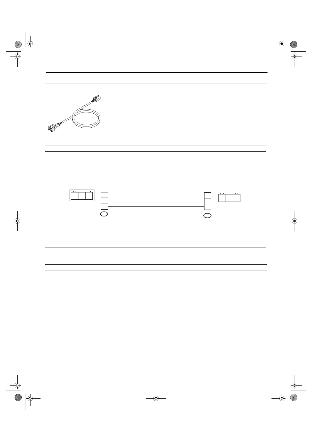
• TEST HARNESS AD
2. GENERAL TOOL
ILLUSTRATION
TOOL NUMBER
DESCRIPTION
REMARKS
98299XA020
TEST HARNESS
AD
Used when measuring voltage and resistance of
the seat belt tension sensor.
TOOL NAME
REMARKS
Circuit tester
Used for measuring resistance, voltage and current.
ST98299XA020
OD-00028
1AD
2AD
3
2
1
3
1
2
3
2
1
3
1
2