Subaru Impreza 3 / Impreza WRX / Impreza WRX STI. Manual - part 503
DI-57
Rear Differential Front Member
DIFFERENTIALS
7. Rear Differential Front Mem-
ber
A: REMOVAL
1) Disconnect the ground cable from battery.
2) Lift up the vehicle.
3) Support the rear differential using transmission
jack, and then remove the rear differential front
member.
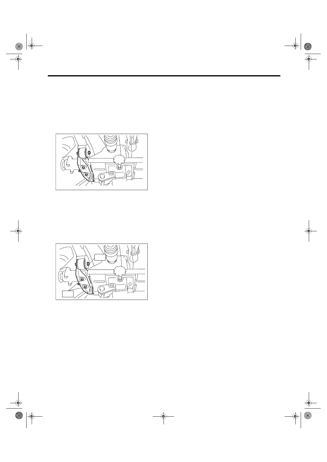
B: INSTALLATION
Install the rear differential front member with a new
self-locking nut.
Tightening torque:
T1: 50 N·m (5.1 kgf-m, 36.9 ft-lb)
T2: 110 N·m (11.2 kgf-m, 81.1 ft-lb)
C: INSPECTION
1) Check the rear differential front member for
damage, bend and corrosion.
If damage, bend or corrosion is excessive, replace
the rear differential front member.
2) Check the bushings of rear differential front
member for cracking, hardening and damage.
If cracking, hardening or damage is excessive, re-
place rear differential front member.
(A) Rear differential front member
DI-00540
(A)
DI-00541
T2
T1