Subaru Impreza 3 / Impreza WRX / Impreza WRX STI. Manual - part 423
6MT-29
Transmission Mounting System
MANUAL TRANSMISSION AND DIFFERENTIAL
5. Transmission Mounting Sys-
tem
A: REMOVAL
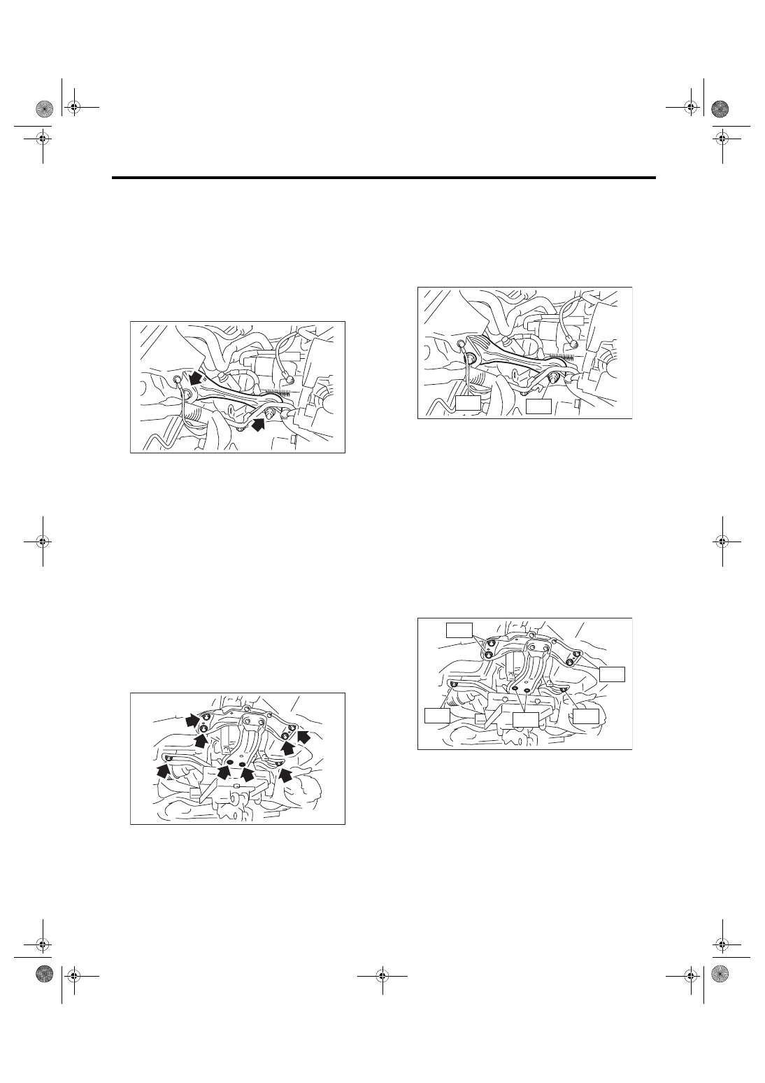
1. PITCHING STOPPER
1) Disconnect the ground cable from battery.
2) Remove the intercooler. <Ref. to IN(STI)-12,
3) Remove the pitching stopper.
2. CROSSMEMBER AND CUSHION RUB-
BER
1) Disconnect the ground cable from battery.
2) Lift up the vehicle.
3) Remove the transmission under cover.
4) Remove the center exhaust pipe. <Ref. to
EX(STI)-8, REMOVAL, Center Exhaust Pipe.>
5) Remove the rear exhaust pipe and muffler.
<Ref. to EX(STI)-13, REMOVAL, Rear Exhaust
Pipe.> <Ref. to EX(STI)-15, REMOVAL, Muffler.>
6) Remove the heat shield cover.
7) Set the transmission jack under the transmission
body.
CAUTION:
Always support the transmission case with a
transmission jack.
8) Remove the rear crossmember.
9) Remove the transmission cushion rubber.
B: INSTALLATION
1. PITCHING STOPPER
1) Install the pitching stopper.
Tightening torque:
T1: 50 N·m (5.1 kgf-m, 36.9 ft-lb)
T2: 58 N·m (5.9 kgf-m, 42.8 ft-lb)
2) Install the intercooler. <Ref. to IN(STI)-13, IN-
3) Connect the ground cable to battery.
2. CROSSMEMBER AND CUSHION RUB-
BER
1) Install the transmission cushion rubber.
Tightening torque:
35 N·m (3.6 kgf-m, 25.8 ft-lb)
2) Install the crossmember.
Tightening torque:
T1: 35 N·m (3.6 kgf-m, 25.8 ft-lb)
T2: 70 N·m (7.1 kgf-m, 51.6 ft-lb)
T3: 140 N·m (14.3 kgf-m, 103 ft-lb)
3) Remove the transmission jack.
4) Install the heat shield cover.
5) Install the rear exhaust pipe and muffler. <Ref. to
EX(STI)-13, INSTALLATION, Rear Exhaust Pipe.>
<Ref. to EX(STI)-15, INSTALLATION, Muffler.>
6) Install the center exhaust pipe. <Ref. to EX(STI)-
9, INSTALLATION, Center Exhaust Pipe.>
MT-01938
MT-01939
MT-01301
T1
T2
MT-01940
T2
T3
T3
T2
T1