Subaru Impreza 3 / Impreza WRX / Impreza WRX STI. Manual - part 402
5MT-29
Transmission Mounting System
MANUAL TRANSMISSION AND DIFFERENTIAL
4. Transmission Mounting Sys-
tem
A: REMOVAL
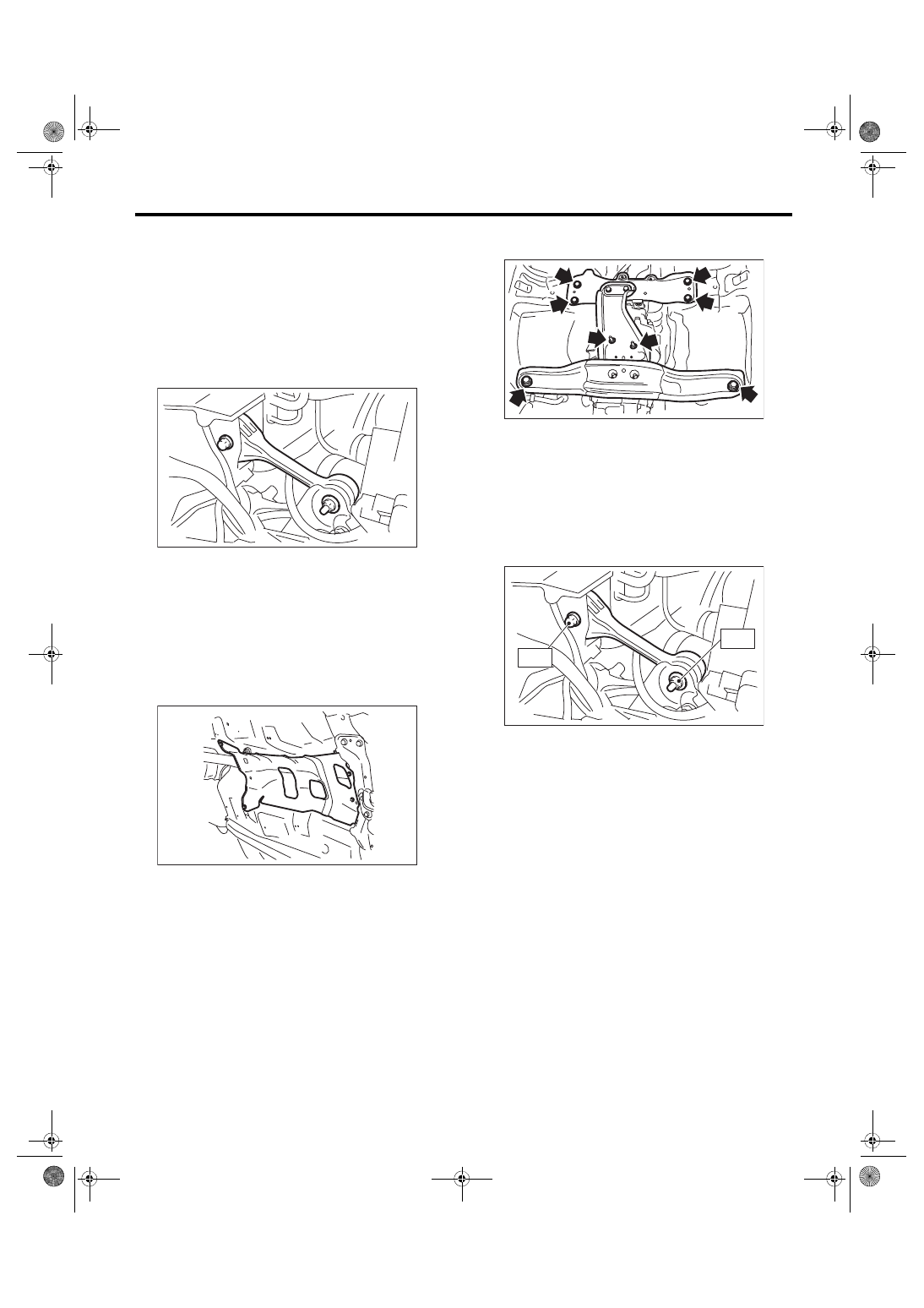
1. PITCHING STOPPER
1) Disconnect the ground cable from battery.
2) Remove the intercooler. <Ref. to IN(w/o STI)-12,
3) Remove the pitching stopper.
2. CROSSMEMBER AND CUSHION RUB-
BER
1) Disconnect the ground cable from battery.
2) Lift up the vehicle.
3) Remove the center exhaust pipe. <Ref. to EX(w/
o STI)-2, General Description.>
4) Remove the rear exhaust pipe and muffler.
<Ref. to EX(w/o STI)-2, General Description.>
5) Remove the heat shield cover.
6) Set the transmission jack under the transmission
case.
CAUTION:
Always support the transmission case with a
transmission jack.
7) Remove the front crossmember and the rear
crossmember.
8) Remove the transmission cushion rubber.
B: INSTALLATION
1. PITCHING STOPPER
1) Install the pitching stopper.
Tightening torque:
T1: 50 N·m (5.1 kgf-m, 36.9 ft-lb)
T2: 58 N·m (5.9 kgf-m, 42.8 ft-lb)
2) Install the intercooler.
<Ref. to IN(w/o STI)-12, INSTALLATION, Inter-
3) Connect the battery ground terminal.
MT-00069
MT-01660
MT-01851
MT-00085
T2
T1