Subaru Impreza 3 / Impreza WRX / Impreza WRX STI. Manual - part 299
EN(H4DOTC)(diag)-420
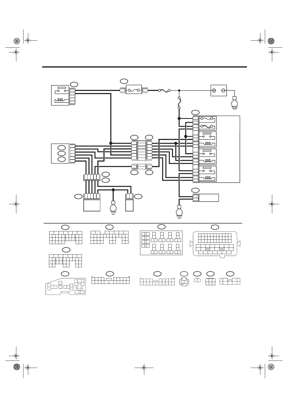
Diagnostic Procedure with Diagnostic Trouble Code (DTC)
ENGINE (DIAGNOSTICS)
• Models with SI-DRIVE <Ref. to WI-48, WITH SI-DRIVE, WIRING DIAGRAM, Engine Electrical System.>
EN-08735
F9
13
12
11
14
1
2
2
1
3
4
16
15
5
6
B143
F37
B144
B21
E2
E40
E41
B134
A:
A:
B135
B:
B135
B:
B137
D:
F37
F11
F9
10A
60A
9
10
8
7
11
5
20
8
B8
B20
B27
A19
D9
A29
6
1
2
8
47
3
2
1
6
4
1
2
9
2
16
18
14
12
10
4
14
4
B134
46
B220
24
23
22
21
B137
D:
31
30
29
28
27
21
20
19
18
17
16
26
25
24
15
14
13
12
11
23
22
10
3
4
9
1
2
8
7
6
5
F11
1 2
29
4
3
1
2
7
6
5
10 11 12 13 14 15
25
24
16
30
9
8
17 18 19
20
28
21 22 23
32
31
26 27
33
34 35
B220
18
19
6
7
4
3
5
2
1
12
11
10
9
8
40
36 39
38
37
34
33
35
32
28 31
30
29
23
22
21
20
26
25
24
27
17
16
15
14
13
4
3
B220
15A
16
15
8
7
4
14
13
11
12
10
9
2
1
3
6
5
B143
20
19
18
17
16
15
14
13
12
11
10
9
8
7
6
5
4
3
2
1
F37
20
19
18
17
16
15
14
13
12
11
10
9
8
7
6
5
4
3
2
1
B144
3
8
2
6
7
1
5
4
9
31
30
32
29
34
33
21
20
19
18
17
16
28
27
26
15
14
13
12
11
25
23
22
24
10
3
4
9
1
2
8
7
6
5
E40
2
6
5
4
3
1
E41
2
1
54
52 53
50 51
48 49
46 47
45
44
42 43
40 41
38 39
36 37
34 35
33
32
31
30
29
28
27
26
25
24
23
22
21
20
11
10
9
19
18
17
16
8
7
6
5
15
14
13
12
4
3
2
1
B21
E
E
E
ECM
SBF-7
FUSE
(RELAY BLOCK)
MAIN SBF
MAIN RELAY
SECONDARY
AIR COMBINATION
VALVE RELAY 2
SECONDARY
AIR PUMP
RELAY
SECONDARY
AIR COMBINATION
VALVE RH
SECONDARY
AIR COMBINATION
VALVE LH
(WITH BUILT-IN
PRESSURE SENSOR)
SECONDARY
AIR COMBINATION
VALVE RELAY 1
SECONDARY
AIR PUMP
MAIN FUSE BOX
(M/B)
RELAY HOLDER
BATTERY