Subaru Impreza 3 / Impreza WRX / Impreza WRX STI. Manual - part 213
EN(H4DOTC)(diag)-76
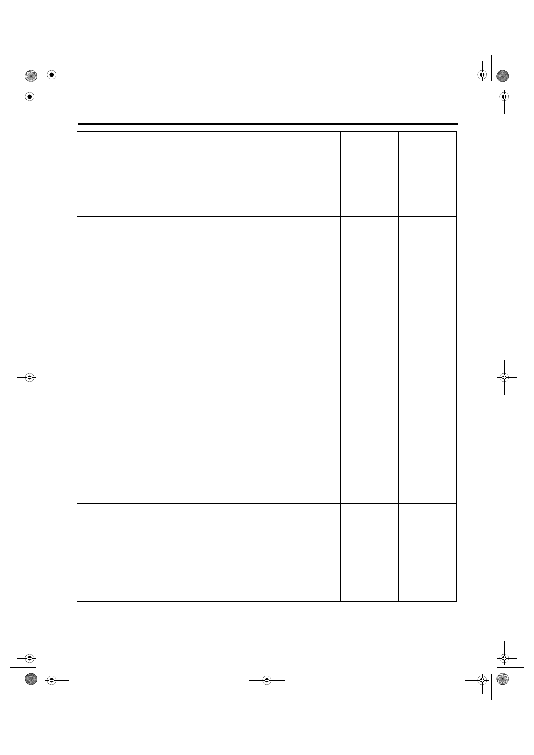
Diagnostics for Engine Starting Failure
ENGINE (DIAGNOSTICS)
3
CHECK DTC.
Is DTC displayed? <Ref. to
EN(H4DOTC)(diag)-48,
OPERATION, Read Diagnostic
Trouble Code (DTC).>
4
CHECK INPUT SIGNAL FOR STARTER MO-
TOR.
1) Turn the ignition switch to OFF.
2) Disconnect the connector from starter
motor.
3) Depress the clutch pedal.
4) Turn the ignition switch to START.
5) Measure the voltage between the starter
motor connector and the engine ground.
Connector & terminal
(B14) No. 1 (+) — Engine ground (–):
Is the voltage 10 V or more?
Check the starter
motor. <Ref. to
SC(STI)-8,
Starter.>
5
CHECK INPUT SIGNAL FOR STARTER MO-
TOR.
1) Depress the clutch pedal.
2) Turn the ignition switch to START.
3) Measure the voltage between starter relay
connector and chassis ground.
Connector & terminal
(B225) No. 10 (+) — Chassis ground (–):
Is the voltage 10 V or more?
Repair the open
circuit of the har-
ness between
starter relay con-
nector and starter
motor.
6
CHECK HARNESS BETWEEN BATTERY
AND IGNITION SWITCH CONNECTOR.
1) Turn the ignition switch to OFF.
2) Disconnect the connector from ignition
switch.
3) Measure the voltage between ignition
switch connector and chassis ground.
Connector & terminal
(B72) No. 3 (+) — Chassis ground (–):
Is the voltage 10 V or more?
Repair the power
supply circuit.
7
CHECK IGNITION SWITCH.
Measure the resistance between ignition switch
terminals after turning the ignition switch to
START position.
Terminals
No. 2 — No. 3:
No. 6 — No. 3:
Is the resistance less than 1 Ω? Go to step
Replace the igni-
tion switch. <Ref.
to SL-42,
REPLACEMENT,
Ignition Key Lock.>
8
CHECK INPUT VOLTAGE OF CLUTCH
START SWITCH.
1) Turn the ignition switch to OFF.
2) Disconnect the clutch start switch connec-
tor.
3) Connect the connector to ignition switch.
4) Turn the ignition switch to START.
5) Measure the voltage between the clutch
start switch connector and chassis ground.
Connector & terminal
(B106) No. 1 (+) — Chassis ground (–):
Is the voltage 10 V or more?
Check the follow-
ing item and repair
if necessary.
• Blown out of fuse
(F/B No. 21)
• Open or short
circuit to ground in
harness between
ignition switch con-
nector and clutch
start switch con-
nector
Step
Check
Yes
No