Subaru Impreza 3 / Impreza WRX / Impreza WRX STI. Manual - part 210


  Index      Subaru     Subaru Impreza 3 / Impreza WRX / Impreza WRX STI - service repair manual 2008-2014 year


Search            


Content   ..  208  209  210  211   ..


Subaru Impreza 3 / Impreza WRX / Impreza WRX STI. Manual - part 210


EN(H4DOTC)(diag)-64

Compulsory Valve Operation Check Mode

ENGINE (DIAGNOSTICS)

14.Compulsory Valve Operation 

Check Mode

A: OPERATION

1) Prepare the Subaru Select Monitor kit. <Ref. to

EN(H4DOTC)(diag)-8,  PREPARATION  TOOL,

General Description.>

2) Prepare  PC  with  Subaru  Select  Monitor  in-

stalled.

3) Connect the USB cable to SDI (Subaru Diagno-

sis Interface) and USB port on the personal com-

puter  (dedicated  port  for  the  Subaru  Select

Monitor).
NOTE:

The dedicated port for the Subaru Select Monitor

means the USB port which was used to install the

Subaru Select Monitor.

4) Connect the diagnosis cable to SDI.

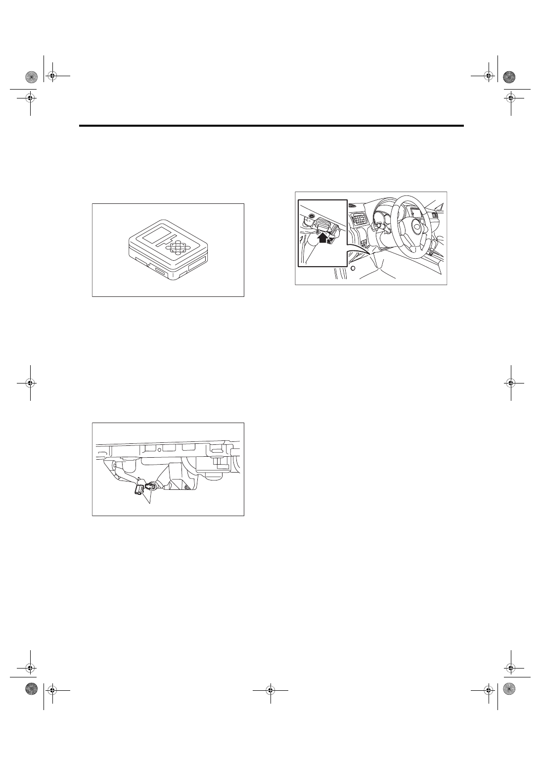
5) Connect the delivery (test) mode connector (A)

located under the glove box.

6) Connect SDI to data link connector located in the

lower portion of the instrument panel (on the driv-

er’s side).
CAUTION:

Do not connect the scan tools except for Suba-

ru Select Monitor and general scan tool.

7) Start the PC.

8) Turn the ignition switch to ON (engine OFF) and

run the “PC application for Subaru Select Monitor”.

9) On «Main Menu» display, select {Each System

Check}.

10) On  «System  Selection  Menu»  display,  select

{Engine Control System}.

11) Click  the  [OK]  button  after  the  information  of

engine type has been displayed.

12) On  «Engine  Diagnosis»  display,  select  {Sys-

tem Operation Check Mode}.

13) On «System Operation Check Mode» display,

select {Actuator ON/OFF Operation}.

14) Select the actuator to be forcibly driven on the

«Actuator ON/OFF Operation» display screen and

click the [Next] button.

15) Clicking  the  [Finished]  button  completes  the

compulsory drive mode of actuator. The display will

then  return  to  the  «Actuator  ON/OFF  Operation»

screen.
NOTE:

For detailed operation procedures, refer to “PC ap-

plication help for Subaru Select Monitor”.

EN-05692

EN-06146

(A)

EN-06148

EN(H4DOTC)(diag)-65

System Operation Check Mode

ENGINE (DIAGNOSTICS)

15.System Operation Check 

Mode

A: OPERATION

1) Prepare the Subaru Select Monitor kit. <Ref. to

EN(H4DOTC)(diag)-8,  PREPARATION  TOOL,

General Description.>

2) Prepare  PC  with  Subaru  Select  Monitor  in-

stalled.

3) Connect the USB cable to SDI (Subaru Diagno-

sis Interface) and USB port on the personal com-

puter  (dedicated  port  for  the  Subaru  Select

Monitor).
NOTE:

The dedicated port for the Subaru Select Monitor

means the USB port which was used to install the

Subaru Select Monitor.

4) Connect the diagnosis cable to SDI.

5) Connect SDI to data link connector located in the

lower portion of the instrument panel (on the driv-

er’s side).
CAUTION:

Do not connect the scan tools except for Suba-

ru Select Monitor and general scan tool.

6) Start the PC.

7) Turn the ignition switch to ON (engine OFF) and

run the “PC application for Subaru Select Monitor”.

8) On «Main Menu» display, select {Each System

Check}.

9) On  «System  Selection  Menu»  display,  select

{Engine Control System}.

10) Click  the  [OK]  button  after  the  information  of

engine type has been displayed.

11) On  «Engine  Diagnosis»  display,  select  {Sys-

tem Operation Check Mode}.

12) The following items are displayed on the moni-

tor.

1. FUEL PUMP CONTROL (OFF DRIVE)

CAUTION:

After  executing  the  system  operation  check

mode, execute the Clear Memory Mode. <Ref. to

EN(H4DOTC)(diag)-63, 

OPERATION, 

Clear

Memory Mode.>

1) On  «System  Operation  Check  Mode»  display,

select {Fuel Pump Control}.

2) On  «Fuel  Pump  Control»  display,  select  {OFF

Drive}.

3) On «Start the Engine» display, start the engine

and click the [OK] button.

4) On  «OFF  Drive»  display,  click  the  [Execution]

button and execute the OFF drive.

5) Click the [Cancel] button to stop the OFF drive.

6) Click the [  Exit] button to end the OFF drive.

The screen will return to the «Fuel Pump Control»

screen.
NOTE:

For detailed operation procedures, refer to “PC ap-

plication help for Subaru Select Monitor”.

2. FUEL PUMP CONTROL (ON/OFF DRIVE)

CAUTION:

After  executing  the  system  operation  check

mode, execute the Clear Memory Mode. <Ref. to

EN(H4DOTC)(diag)-63, 

OPERATION, 

Clear

Memory Mode.>

1) On  «System  Operation  Check  Mode»  display,

select {Fuel Pump Control}.

2) On  «Fuel  Pump  Control»  display,  select  {ON/

OFF Dr.}.

3) On «Turn Ignition Switch ON with Engine OFF»

display, turn the ignition switch to ON and click the

[OK] button.

4) On «ON/OFF Dr.» display, click the [Execution]

button and execute the ON/OFF drive.

5) Click  the  [Cancel]  button  to  stop  the  ON/OFF

drive.

EN-05692

EN-06148

Display

Actuator ON/OFF Operation
Immobilizer System
Fuel Pump Control
Fixed Idle Ignition Timing
Idle Speed Control
Injector Control

EN(H4DOTC)(diag)-66

System Operation Check Mode

ENGINE (DIAGNOSTICS)

6) Click  the  [   Exit]  button  to  end  the  ON/OFF

drive.  The  screen  will  return  to  the  «Fuel  Pump

Control» screen.
NOTE:

For detailed operation procedures, refer to “PC ap-

plication help for Subaru Select Monitor”.

3. IDLING IGNITION TIMING FIXED

CAUTION:

After  executing  the  system  operation  check

mode, execute the Clear Memory Mode. <Ref. to

EN(H4DOTC)(diag)-63, 

OPERATION, 

Clear

Memory Mode.>

1) On  «System  Operation  Check  Mode»  display,

select {Fixed Idle Ignition Timing}.

2) On «Start the Engine» display, start the engine

and click the [OK] button.

3) On «Fixed Idle Ignition Timing» display, click the

[Execution]  button  and  execute  the  idling  ignition

timing fixed.

4) Click the [Cancel] button to stop the idling igni-

tion timing fixed.

5) Click the [  Exit] button to end the idle ignition

timing fixed. The screen will return to the «System

Operation Check Mode» screen.
NOTE:

For detailed operation procedures, refer to “PC ap-

plication help for Subaru Select Monitor”.

4. IDLE SPEED CONTROL

CAUTION:

After  executing  the  system  operation  check

mode, execute the Clear Memory Mode. <Ref. to

EN(H4DOTC)(diag)-63, 

OPERATION, 

Clear

Memory Mode.>

1) On  «System  Operation  Check  Mode»  display,

select {Idle Speed Control}.

2) On «Start the Engine» display, start the engine

and click the [OK] button.

3) In the «Idle Speed Control» display, click the [ ]

button or the [ ] button to change the setting val-

ues, then click the [OK] button.

Setting is possible in a range between 500 rpm —

2,000 rpm, in increments of 50 rpm. However, the

engine  speed  that  can  actually  be  controlled  will

vary depending on the vehicle.

4) Click the [Cancel] button to stop the idle speed

control.

5) Click the [  Exit] button to end the idle speed

control. The screen will return to the «System Op-

eration Check Mode» screen.
NOTE:

For detailed operation procedures, refer to “PC ap-

plication help for Subaru Select Monitor”.

5. INJECTOR CONTROL (INJECTION STOP 

MODE)

CAUTION:

After  executing  the  system  operation  check

mode, execute the Clear Memory Mode. <Ref. to

EN(H4DOTC)(diag)-63, 

OPERATION, 

Clear

Memory Mode.>

1) On  «System  Operation  Check  Mode»  display,

select {Injector Control}.

2) On  «Injector  Control»  display,  select  {Injection

Stop Mode}.

3) On  «Injection  Stop  Mode»  display,  select  the

fuel injector to be stopped.

4) On «Start the Engine» display, start the engine

and click the [OK] button.

5) On  «Fuel  Injector  #»  display,  click  the  [Execu-

tion] button and execute the injection stop mode.

6) Click  the  [Cancel]  button  to  stop  the  injection

stop mode.

7) Click the [  Exit] button to return the «Injection

Stop Mode» display screen.

8) On the «Injection Stop Mode» display, click the

[Return] button to end the «Injection Stop Mode».

The  screen  will  return  to  the  «Injector  Control»

screen.
NOTE:

For detailed operation procedures, refer to “PC ap-

plication help for Subaru Select Monitor”.

6. INJECTOR CONTROL (INJECTION 

QUANTITY CONTROL)

CAUTION:

After  executing  the  system  operation  check

mode, execute the Clear Memory Mode. <Ref. to

EN(H4DOTC)(diag)-63, 

OPERATION, 

Clear

Memory Mode.>

1) On  «System  Operation  Check  Mode»  display,

select {Injector Control}.

2) On  «Injector  Control»  display,  select  {Injection

Quantity Control}.

3) On «Start the Engine» display, start the engine

and click the [OK] button.

4) In the «Injection Quantity Control» display, click

the [ ] button or the [ ] button to change the set-

ting values, then click the [OK] button.

Setting is possible in a range between 0 — 20%, in

increments of 1%.

5) Click  the  [Cancel]  button  to  stop  the  injection

quantity control.

6) Click  the  [   Exit]  button  to  end  the  injection

quantity control. The screen will return to the «In-

jector Control» screen.
NOTE:

For detailed operation procedures, refer to “PC ap-

plication help for Subaru Select Monitor”.

EN(H4DOTC)(diag)-67

Malfunction Indicator Light

ENGINE (DIAGNOSTICS)

16.Malfunction Indicator Light

A: PROCEDURE

B: ACTIVATION OF MALFUNCTION 

INDICATOR LIGHT

1) When the ignition switch is turned to ON (engine

OFF), the malfunction indicator light (A) in the com-

bination meter illuminates.
NOTE:

If the malfunction indicator light does not illuminate,

perform  diagnostics  of  the  malfunction  indicator

light circuit or the combination meter circuit. <Ref.

to  EN(H4DOTC)(diag)-69,  MALFUNCTION  INDI-

CATOR LIGHT DOES NOT COME ON, Malfunc-

tion Indicator Light.>

2) After starting the engine, the malfunction indica-

tor light goes out. If it does not go off, any of the en-

gine and emission control system has malfunction.

1. Activation of malfunction indicator light. <Ref. to EN(H4DOTC)(diag)-67, ACTIVATION OF MALFUNCTION INDICATOR LIGHT, 
Malfunction Indicator Light.>

2. Malfunction indicator light does not come on. <Ref. to EN(H4DOTC)(diag)-69, MALFUNCTION INDICATOR LIGHT DOES NOT 
COME ON, Malfunction Indicator Light.>

3. Malfunction indicator light does not go off <Ref. to EN(H4DOTC)(diag)-69, MALFUNCTION INDICATOR LIGHT DOES NOT 
GO OFF, Malfunction Indicator Light.>

4. Malfunction indicator light does not blink <Ref. to EN(H4DOTC)(diag)-70, MALFUNCTION INDICATOR LIGHT DOES NOT 
BLINK, Malfunction Indicator Light.>

5. Malfunction indicator light remains blinking <Ref. to EN(H4DOTC)(diag)-72, MALFUNCTION INDICATOR LIGHT REMAINS 
BLINKING, Malfunction Indicator Light.>

(A)

EN-06144

(1) No DTC
(2) Trouble occurs
(3) ON
(4) OFF
(5) Ignition switch ON
(6) Engine start

EN-01679

(1)

(2)

(5)

(6)

(3)

(4)

(3)

(4)


Content   ..  208  209  210  211   ..