Subaru Impreza 3 / Impreza WRX / Impreza WRX STI. Manual - part 195
EN(H4DOTC)(diag)-4
Check List for Interview
ENGINE (DIAGNOSTICS)
2. Check List for Interview
A: CHECK
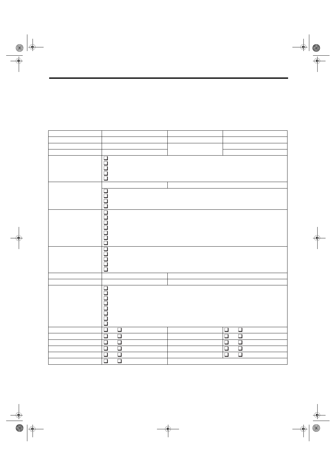
1. CHECK LIST NO. 1
Check the following item when problem has occurred.
NOTE:
Use copies of this page for interviewing customers.
Customer’s name
Engine No.
Date of purchase
Fuel type
Date of repair
Odometer reading
km
V.I.N.
miles
Weather
Fine
Cloudy
Rainy
Snowy
Various/Others:
Ambient air temperature
°C (°F)
Hot
Warm
Cool
Cold
Place
Highway
Suburbs
Inner city
Uphill
Downhill
Rough road
Others:
Engine temperature
Cold
Warming-up
After warming-up
Any temperature
Others:
Engine speed
rpm
Vehicle speed
km/h (MPH)
Driving conditions
Not affected
At starting
While idling
At racing
While accelerating
While cruising
While decelerating
While turning (RH/LH)
Headlight
ON/
OFF
Rear defogger
ON/
OFF
Blower
ON/
OFF
Audio
ON/
OFF
A/C compressor
ON/
OFF
Rear entertainment system
ON/
OFF
Radiator fan
ON/
OFF
Car phone
ON/
OFF
Front wiper
ON/
OFF
Wireless device
ON/
OFF
Rear wiper
ON/
OFF