Subaru Impreza 3 / Impreza WRX / Impreza WRX STI. Manual - part 84
 

  Index      Subaru     Subaru Impreza 3 / Impreza WRX / Impreza WRX STI - service repair manual 2008-2014 year


Search            


Content   ..  82  83  84  85   ..


Subaru Impreza 3 / Impreza WRX / Impreza WRX STI. Manual - part 84


ME(STI)-98

Cylinder Block

MECHANICAL

(2) If  the  cylinder  inner  diameter  exceeds  the

limit after boring and honing, replace the cylin-

der block.

NOTE:

Immediately  after  reboring,  the  cylinder  diameter

may differ from its real diameter due to temperature

rise. Thus, when measuring the cylinder diameter,

wait until it has cooled to room temperature.
Cylinder inner diameter boring limit (diameter):

To 100.005 mm (3.9372 in)

3. PISTON AND PISTON PIN

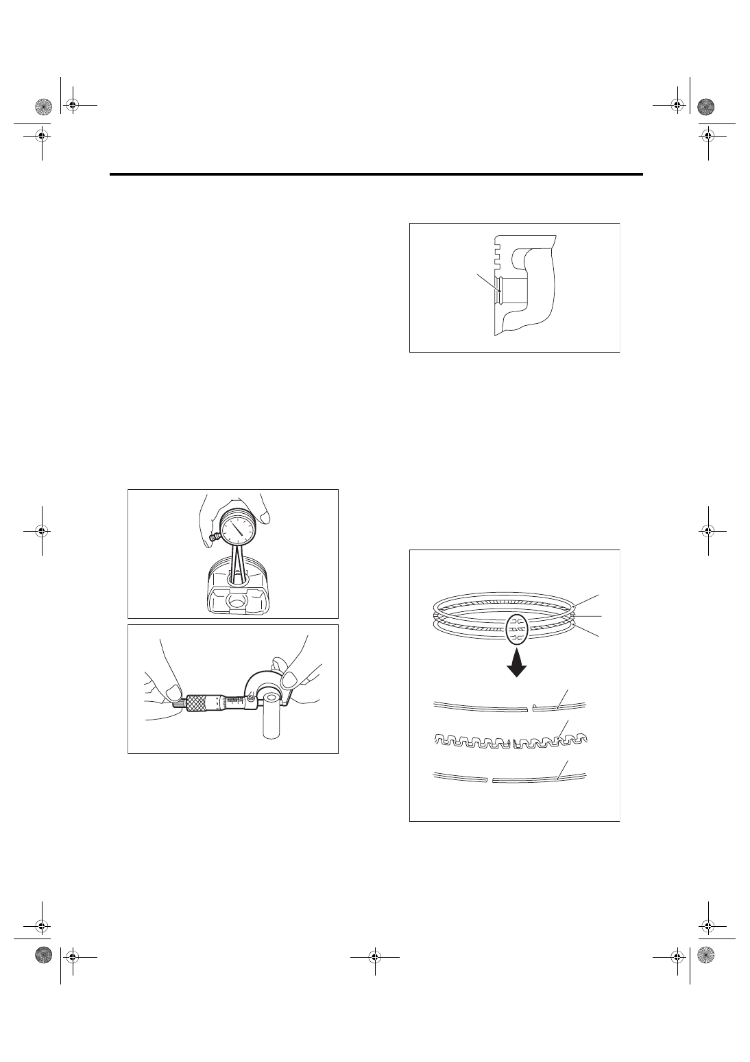
1) Check  the  piston  and  piston  pin  for  damage,

cracks or wear. Replace if faulty.

2) Check the piston ring groove for wear or dam-

age. Replace if faulty.

3) Make  sure  that  the  piston  pin  can  be  inserted

into the piston pin hole with a thumb at 20°C (68°F).

Replace if faulty.
Clearance between piston pin hole and piston 

pin:

Standard

0.004 — 0.008 mm (0.0002 — 0.0003 in)

4) Check  the  snap  ring  installation  groove  (A)  on

the piston for burr. If necessary, remove burr from

the groove so that the piston pin can lightly move.

5) Check  the  snap  ring  for  distortion,  cracks  and

wear.

4. PISTON RING

1) If the piston ring is broken, damaged or worn, or

if its tension is insufficient, or when the piston is re-

placed, replace the piston ring with a new part of

the same size as piston.
NOTE:

• The top ring and second ring have the mark to

determine the direction for installing. When install-

ing the ring to piston, face marks to the top side.

• Oil ring consists of the upper rail, expander and

lower  rail.  When  installing  oil  ring  on  piston,  be

careful of the direction of each rail.

ME-00173

ME-00174

(A) Upper rail
(B) Expander

(C) Lower rail

ME-00175

(A)

ME-02480

(A)

(B)

(C)

(A)

(B)

(C)

ME(STI)-99

Cylinder Block

MECHANICAL

2) Using  the  piston,  insert  the  piston  ring  and  oil

ring into the cylinder block so that they are perpen-

dicular to the cylinder wall, and measure the piston

ring gap using a thickness gauge.

3) Fit  the  piston  ring  straight  into  the  piston  ring

groove, then measure the clearance between pis-

ton  ring  and  piston  ring  groove  with  a  thickness

gauge.
NOTE:

Before measuring the clearance, clean the piston

ring groove and piston ring.

5. CONNECTING ROD

1) Replace the connecting rod, if the large or small

end thrust surface is damaged.

2) Check for bend or twist using a connecting rod

aligner. Replace the connecting rod if the bend or

twist exceeds the limit.
Limit of bend or twist per 100 mm (3.94 in) in 

length:

0.10 mm (0.0039 in)

3) Install the connecting rod with bearings attached

to  the  crankshaft,  and  using  a  thickness  gauge,

measure  the  thrust  clearance.  If  the  thrust  clear-

ance  exceeds  the  standard  or  uneven  wear  is

found, replace the connecting rod.
Connecting rod thrust clearance:

Standard

0.070 — 0.330 mm (0.0028 — 0.0130 in)

4) Inspect  the  connecting  rod  bearing  for  scar,

peeling, seizure, melting, wear, etc.


Standard

mm (in)

Piston ring gap

Top ring

0.23 — 0.28

(0.0091 — 0.0110)

Second ring

0.37 — 0.52

(0.015 — 0.020)

Oil ring rail

0.20 — 0.50

(0.0079 — 0.0197)


Standard

mm (in)

Clearance between 
piston ring and pis-
ton ring groove

Top ring

0.040 — 0.080

(0.0016 — 0.0031)

Second ring

0.030 — 0.070

(0.0012 — 0.0028)

ME-00177

ME-00178

(A) Thickness gauge
(B) Connecting rod

(A)

(A)

(B)

(B)

ME-05475

ME-00180

ME(STI)-100

Cylinder Block

MECHANICAL

5) Measure  the  oil  clearance  on  each  connecting

rod bearing using plastigauge. If any oil clearance

is  not  within  the  standard,  replace  the  defective

bearing with a new part of standard size or under-

size as necessary.
Connecting rod oil clearance:

Standard

0.017 — 0.045 mm (0.0007 — 0.0018 in)

6) Inspect the bushing at connecting rod small end,

and replace the connecting rod if it is worn or dam-

aged.

7) Measure the piston pin clearance at connecting

rod small end. If the measured value is not within

the standard, replace the connecting rod and piston

pin as a set.
Clearance between piston pin and bushing:

Standard

0 — 0.022 mm (0 — 0.0009 in)

6. CRANKSHAFT AND CRANKSHAFT 

BEARING

1) Clean the crankshaft completely, and check it for

cracks using liquid penetrant tester. If defective, re-

place the crankshaft.

2) Measure warping of the crankshaft. If it exceeds

the limit, correct or replace it.
NOTE:

If a suitable V-block is not available, using just the

#1  and  #5  crankshaft  bearings  on  cylinder  block,

position  the  crankshaft  on  cylinder  block.  Then,

measure the crankshaft bend using a dial gauge.
Crankshaft bend limit:

0.035 mm (0.0014 in)

Unit: mm (in)

Bearing

Bearing size

(Thickness at cen-

ter)

Outer diameter of 

crank pin

Standard

1.490 — 1.506

(0.0587 — 0.0593)

51.976 — 52.000

(2.0463 — 2.0472)

0.03 (0.0012)

Undersize

1.504 — 1.512

(0.0592 — 0.0595)

51.954 — 51.970

(2.0454 — 2.0461)

0.05 (0.0020)

Undersize

1.514 — 1.522

(0.0596 — 0.0599)

51.934 — 51.950

(2.0447 — 2.0453)

0.25 (0.0098)

Undersize

1.614 — 1.622

(0.0635 — 0.0639)

51.734 — 51.750

(2.0368 — 2.0374)

ME-00181

ME-00174

ME-00183

ME(STI)-101

Cylinder Block

MECHANICAL

3) Inspect the crank journal and crank pin for wear. If they are not within the standard, replace the bearing

with a suitable (undersize) one, and replace or grind to correct the crankshaft as necessary. When grinding

the crank journal or crank pin, finish them to the specified dimensions according to the undersize bearing to

be used.
Crank pin:

Cylindricality

Limit

0.006 mm (0.0002 in)

Out-of-roundness

Limit

0.005 mm (0.0002 in)

Grinding limit (dia.)

To 51.750 mm (2.0374 in)

Crank journal:

Cylindricality

Limit

0.006 mm (0.0002 in)

Out-of-roundness

Limit

0.005 mm (0.0002 in)

Grinding limit (dia.)

To 59.758 mm (2.3527 in)

ME-00184

Unit: mm (in)


Crank journal diameter

Crank pin outer diameter

#1, #3

#2, #4, #5

Standard

Journal O.D.

59.984 — 60.008

(2.3616 — 2.3625)

59.984 — 60.008

(2.3616 — 2.3625)

51.976 — 52.000

(2.0463 — 2.0472)

Bearing size
(Thickness at center)

1.998 — 2.015

(0.0787 — 0.0793)

2.000 — 2.017

(0.0787 — 0.0794)

1.490 — 1.506

(0.0587 — 0.0593)

0.03 (0.0012)
Undersize

Journal O.D.

59.962 — 59.978

(2.3607 — 2.3613)

59.962 — 59.978

(2.3607 — 2.3613)

51.954 — 51.970

(2.0454 — 2.0461)

Bearing size
(Thickness at center)

2.017 — 2.020

(0.0794 — 0.0795)

2.019 — 2.022

(0.0795 — 0.0796)

1.504 — 1.512

(0.0592 — 0.0595)

0.05 (0.0020)
Undersize

Journal O.D.

59.942 — 59.958

(2.3599 — 2.3605)

59.942 — 59.958

(2.3599 — 2.3605)

51.934 — 51.950

(2.0447 — 2.0453)

Bearing size
(Thickness at center)

2.027 — 2.030

(0.0798 — 0.0799)

2.029 — 2.032

(0.0799 — 0.0800)

1.514 — 1.522

(0.0596 — 0.0599)

0.25 (0.0098)
Undersize

Journal O.D.

59.742 — 59.758

(2.3520 — 2.3527)

59.742 — 59.758

(2.3520 — 2.3527)

51.734 — 51.750

(2.0368 — 2.0374)

Bearing size
(Thickness at center)

2.127 — 2.130

(0.0837 — 0.0839)

2.129 — 2.132

(0.0838 — 0.0839)

1.614 — 1.622

(0.0635 — 0.0639)


Content   ..  82  83  84  85   ..