Subaru Impreza 3 / Impreza WRX / Impreza WRX STI. Manual - part 18


  Index      Subaru     Subaru Impreza 3 / Impreza WRX / Impreza WRX STI - service repair manual 2008-2014 year


Search            


Content   ..  16  17  18  19   ..


Subaru Impreza 3 / Impreza WRX / Impreza WRX STI. Manual - part 18


PM-10

V-belt

PERIODIC MAINTENANCE SERVICES

6. V-belt

A: INSPECTION

CAUTION:

Check and adjust the front side belt tension so

that it is within the specified range. Using the

belt  with  a  tension  out  of  the  specified  range

may result in a fault such as the following:

• If the front side belt tension is higher, unex-

pected force is generated at the power steering

oil  pump,  generator  and  crankshaft  bearing,

causing abnormal noise due to abnormal wear

of the bearing.

• If the front side belt tension is lower, the front

side belt and crank pulley slip, causing abnor-

mally high temperature on the crank pulley due

to  frictional  heat.  If  this  condition  repeatedly

occurs,  the  front  side  belt  may  abnormally

wear,  causing  abnormal  noise,  front  side  belt

damage or crank pulley damage.
NOTE:

Since the rear belt is a stretch type belt, it does not

require tension check and adjustment.

1. PROCEDURE (WITHOUT BELT TEN-

SION GAUGE)

1) Replace the belts if cracks, fraying or wear are

found.

2) Check the V-belt tension and adjust it if neces-

sary by changing the generator installing position

or  idler  pulley  installing  position.  <Ref.  to  PM-10,

REPLACEMENT, V-belt.>
When pressing with belt tension 98 N (10 kgf, 22 

lbf)

When replacing: 7 — 9 mm (0.276 — 0.354 in)

When reusing: 9 — 11 mm (0.354 — 0.433 in)

2. PROCEDURE (WITH BELT TENSION 

GAUGE)

1) Replace the belts if cracks, fraying or wear are

found.

2) Remove the V-belt covers and radiator reservoir

tank.

3) Check  the  belt  tension,  using  the  belt  tension

gauge. Adjust the tension, if necessary by chang-

ing the generator installing position or idler pulley

installing position.
Belt tension

When installing new parts:

640 — 780 N (65 — 80 kgf, 144 — 175 lbf)

At inspection:

490 — 640 N (50 — 65 kgf, 110 — 144 lbf)

B: REPLACEMENT

1. FRONT SIDE BELT (FOR POWER 

STEERING OIL PUMP AND GENERATOR)

NOTE:

Wipe off any oil or water on the belt and pulley.

1) Remove the V-belt covers.

2) Loosen the lock bolt (A).

3) Loosen the slider bolt (B).

4) Remove the front side belt (C).
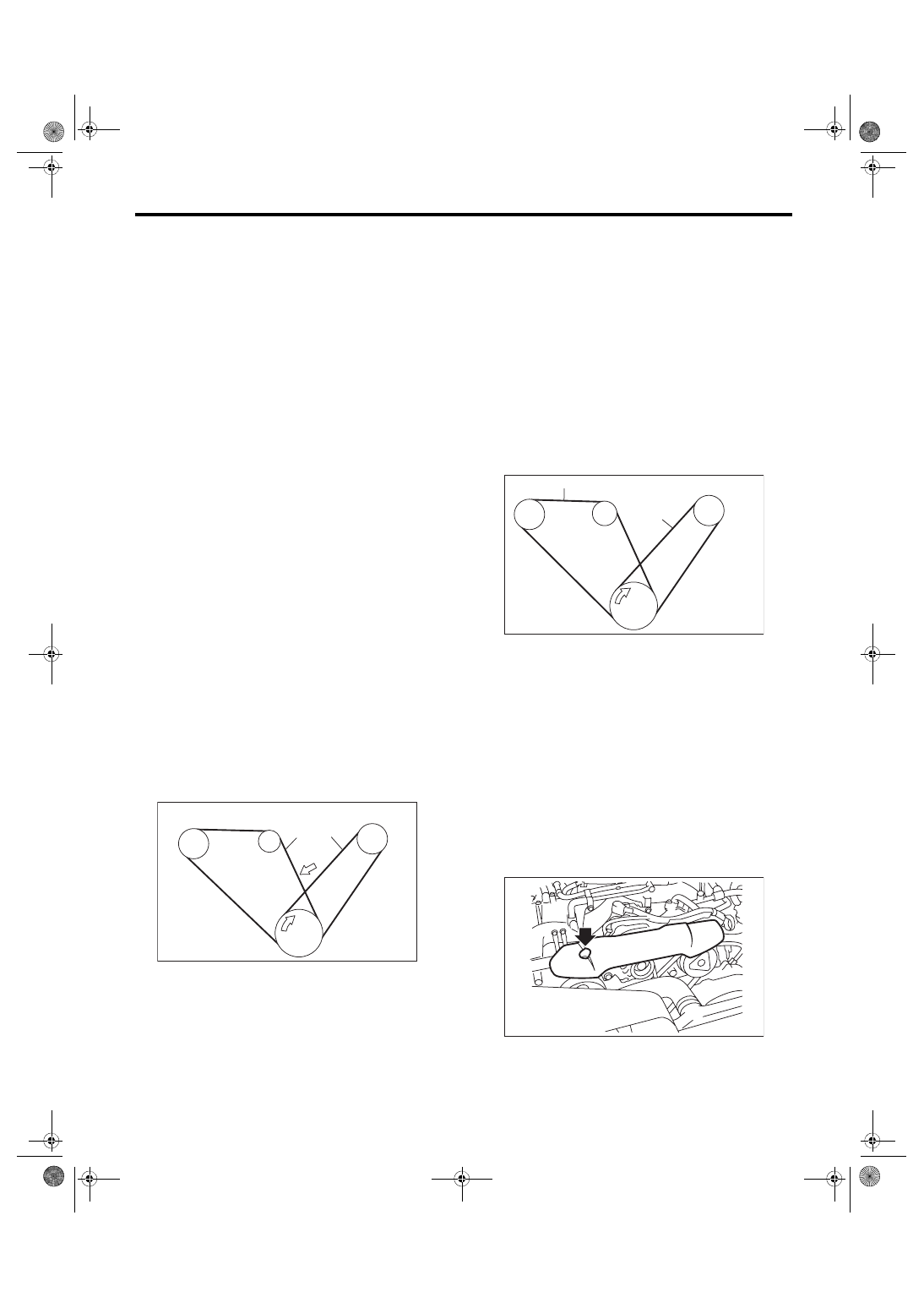
(A) Front side belt
(B) Rear side belt

(C) 98 N (10 kgf, 22 lbf)

C/P Crank pulley

GEN Generator pulley

P/S Power steering oil pump pulley

A/C A/C compressor pulley

ME-03314

(A)

(B)

GEN

C/P

A/C

P/S

(C)

(A) Front side belt
(B) Rear side belt

C/P Crank pulley

GEN Generator pulley

P/S Power steering oil pump pulley

A/C A/C compressor pulley

ME-03313

C/P

P/S

A/C

GEN

(A)

(B)

PM-00378

PM-11

V-belt

PERIODIC MAINTENANCE SERVICES

5) Install a new belt, and tighten the slider bolt so as

to obtain the specified belt tension.

6) Tighten the lock bolt (A).

7) Tighten the slider bolt (B).
Tightening torque:

Lock bolt

25 N·m (2.5 kgf-m, 18.4 ft-lb)

Slider bolt

8 N·m (0.8 kgf-m, 5.9 ft-lb)

8) Start and run the engine for approximately five

minutes to allow the V-belt to become fitted. (When

using the gauge)

9) Stop the engine, check the belt tension and ad-

just as necessary. (When using the gauge)

10) Start and run the engine for approximately one

minute to allow the V-belt to become fitted. (When

using the gauge)

11) Stop the engine and check that the belt tension

is within the specification. (When using the gauge)

12) Adjust  until  the  specified  belt  tension  is  ob-

tained. (When using the gauge)

2. REAR SIDE BELT (FOR A/C)

CAUTION:

Always use new rear side belt.

1) Remove the front side belts.

2) Cut the rear side belt.

3) Install a new belt using an installation jig. <Ref.

to  ME(STI)-41,  REAR  SIDE  BELT,  INSTALLA-

TION,  V-belt.>  <Ref.  to  ME(w/o  STI)-39,  REAR

SIDE BELT, INSTALLATION, V-belt.>

4) Install the front side belt.  <Ref.  to  ME(STI)-40,

INSTALLATION, V-belt.> <Ref. to ME(w/o STI)-38,

INSTALLATION, V-belt.>

PM-00379

(B)

(A)

(C)

PM-12

Timing Belt

PERIODIC MAINTENANCE SERVICES

7. Timing Belt

A: INSPECTION

1. CHECK TIMING BELT POSITION

1) Remove the timing belt cover (LH) and (RH).

2) Turn the crank pulley and align single line mark

(A) on the intake cam sprocket (RH) with notch (B)

on timing belt cover and check the following.

(1) Make  sure  double  lines  (C)  on  intake  and

exhaust cam sprocket (RH side) are aligned.

(2) Make  sure  single  line  (D)  on  exhaust  cam

sprocket (RH side) is aligned to timing belt cov-

er notch (E).

(3) Make  sure  single  line  (A)  on  intake  cam

sprocket (LH side) is aligned to timing belt cover

notch (B).

(4) Make  sure  double  lines  (C)  on  intake  and

exhaust cam sprocket (LH side) are aligned.

(5) Check that the single line mark (D) on the

exhaust cam sprocket (LH side) and notch (E)

on the timing belt cover are aligned.

3) When cam sprocket position is offset, check for

any defect, and repair or replace as required.

2. OTHER INSPECTIONS

1) Remove the timing belt cover (LH).

2) While  cranking  engine  at  least  four  rotations,

check  the  timing  belt  back  surface  for  cracks  or

damage. Replace faulty timing belts with new parts

as required.

3) When the side part of timing belt (arrow direction

shown  in  the  figure)  is  abnormally  worn  (fluff  or

jumping out of core) or damaged, check the idlers,

tensioner, water pump pulley and cam sprocket to

determine  idler  alignment  (squareness).  Replace

the worn timing belt with new part.

4) Install the timing belt cover (LH).

PM-00538

(D)

(E)

(C)

(A)

(B)

PM-00539

(D)

(E)

(C)

(A)

(B)

PM-00343

PM-13

Timing Belt

PERIODIC MAINTENANCE SERVICES

B: REPLACEMENT

1) Remove the radiator fan and air conditioner fan.

<Ref. to CO(STI)-23, Radiator Main Fan and Fan

Motor.>  <Ref.  to  CO(STI)-25,  Radiator  Sub  Fan

and Fan Motor.> <Ref. to CO(w/o STI)-23, Radiator

Main Fan and Fan Motor.> <Ref. to CO(w/o STI)-

25, Radiator Sub Fan and Fan Motor.>

2) Protect the radiator with cardboard and blanket.

3) Remove the V-belt covers.

4) Remove  the  V-belts.  <Ref.  to  ME(STI)-40,  V-

belt.> <Ref. to ME(w/o STI)-38, V-belt.>

5) Remove the crank pulley. <Ref. to ME(STI)-47,

REMOVAL, Crank Pulley.> <Ref. to ME(w/o STI)-

45, REMOVAL, Crank Pulley.>

6) Remove the timing belt cover. <Ref. to ME(STI)-

49,  REMOVAL,  Timing  Belt  Cover.>  <Ref.  to

ME(w/o STI)-47, REMOVAL, Timing Belt Cover.>

7) Using ST, turn the crankshaft and align the align-

ment  marks  on  crankshaft  and  left  and  right  cam

sprockets with alignment marks of belt cover and

oil pump.

ST 499987500

CRANKSHAFT SOCKET

8) Remove the belt idler.

9) Remove the timing belt.

10) Remove the automatic belt tension adjuster as-

sembly.

11) Install in the reverse order of removal. <Ref. to

ME(STI)-52, INSTALLATION, Timing Belt.> <Ref.

to ME(w/o STI)-50, INSTALLATION, Timing Belt.>
CAUTION:

When installing the timing belt, be sure to align

all  alignment  marks  on  the  belt  with  corre-

sponding marks on the sprockets. If incorrectly

installed,  interference  between  pistons  and

valves may occur.

PM-00378

ME-00070

PM-00555

PM-00521

PM-00096


Content   ..  16  17  18  19   ..