Subaru Legacy (2005 year). Manual - part 849
PS-67
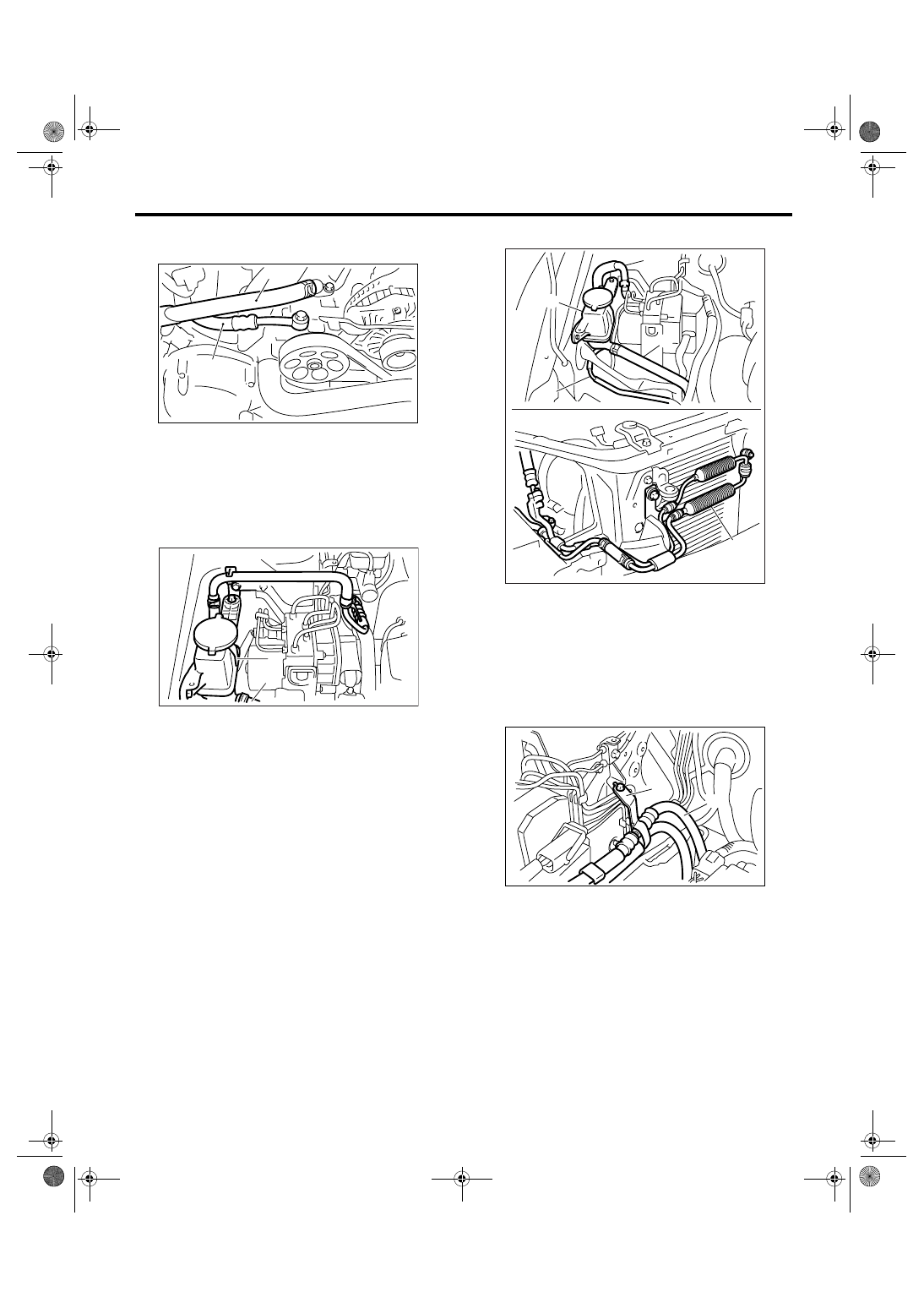
POWER ASSISTED SYSTEM (POWER STEERING)
Pipe Assembly [LHD Model]
7) Disconnect the suction hose and pressure hose
from oil pump.
8) Disconnect the suction hose and return hose
from reservoir tank. Remove the oil cooler from oil
cooler bracket.
• H4 model
• H6 model
9) Remove the hose bracket and take out the hose
assembly from vehicle.
(1) Suction hose
(2) Pressure hose
(1) Reservoir tank
(2) Suction hose
(3) Return hose
PS-00688
(1)
(2)
PS-00697
(1)
(2)
(3)
(1) Reservoir tank
(2) Suction hose
(3) Return hose
(4) Oil cooler pipe
(5) Oil cooler
(1) Hose ASSY
(2) Hose bracket
(3)
(4)
(5)
PS-00623
(2)
(1)
PS-00624
(2)
(1)