Subaru Legacy (2005 year). Manual - part 826


  Index      Subaru     Subaru Legacy - service repair manual 2005 year


Search            


Content   ..  824  825  826  827   ..


Subaru Legacy (2005 year). Manual - part 826


BR-33

BRAKE

Brake Booster

9. Brake Booster

A: REMOVAL

1) Remove or disconnect the following parts at en-
gine compartment.

(1) Disconnect the connector for brake fluid lev-
el gauge.
(2) Remove the brake pipes from master cylin-
der.
(3) Remove the master cylinder installing nuts.
(4) Disconnect the vacuum hose from brake
booster.

2) Remove the following parts from pedal bracket.

(1) Snap pin and clevis pin
(2) Four brake booster installing nuts

3) Remove the brake booster while shunning brake
pipes.

NOTE:
• Do not apply strong impact to booster shell and
vacuum pipe.
• Be careful not to drop the brake booster. The
brake booster should be replaced if it has been
dropped.
• Use special care when handling the operating
rod. If excessive force is applied to operating rod,
sufficient to cause a change in the angle in excess
of 

±3°, it may result in damage to the power piston

cylinder.

• Use care when placing the brake booster on the
floor.
• Do not change the push rod length.
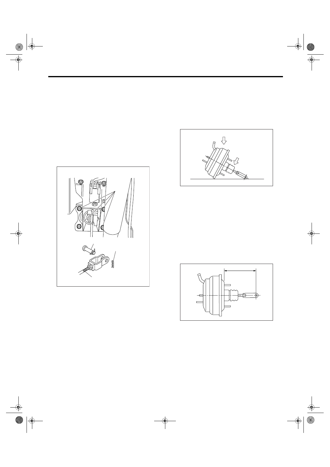
CAUTION:
• Do not disassemble the brake booster.
• If external force is applied from above when
brake booster is placed in this position, the res-
in portion as indicated by “P” may be damaged.

B: INSTALLATION

1) Check and adjust the operating rod of brake
booster.

Specification L:

LHD

136.3 mm (5.38 in)

RHD

155.2 mm (6.11 in)

If it is not within the specification, adjust it by the
brake booster operating rod.

2) Mount the brake booster in position.

(1) Nut

(2) Clevis pin

(3) Snap pin

(4) Operating rod

(1)

(3)

(4)

(2)

BR-00073

(1) Force

(1)

P

BR-00075

L

BR-00076

BR-34

BRAKE

Brake Booster

3) Connect the operating rod to brake pedal with
clevis pin and snap pin.

NOTE:
Apply a thin coat of grease [SUNLIGHT 2 (Part No.
003602010)] to clevis pin.
4) Connect the vacuum hose to brake booster.
5) After replacing the O-ring with a new one, install
the master cylinder to brake booster.

6) Connect the brake pipes to master cylinder.
7) Connect the connector for brake fluid level
gauge.

8) Measure the clearance between the threaded
end of stop light switch and stopper.
If it is not within specification, adjust the position of
stop light switch. <Ref. to BR-46, ADJUSTMENT,
Stop Light Switch.>

CAUTION:
Be careful not to rotate the stop light switch.

Stop light switch clearance A:

0.3 mm (0.012 in)

9) Apply grease to the operating rod connecting pin
to prevent it from wearing.
10) Bleed air from brake system.

Tightening torque (Air bleeder screw):

8 N

m (0.8 kgf-m, 5.9 ft-lb)

11) Conduct road tests to ensure brakes do not
drag.

C: INSPECTION

1. OPERATION CHECK (WITHOUT GAUG-
ES)

CAUTION:
When checking operation, be sure to securely 
apply the parking brake.
• CHECKING WITHOUT GAUGES

This method cannot determine the exact portion
which has failed. But it can provide a rough under-
standing of the nature of failure if checking is con-
ducted in accordance with the following
procedures.

(1) Nut

(2) Clevis pin

(3) Snap pin

(4) Operating rod

(1) Primary piston

(2) O-ring

(3) Do not install the O-ring on this groove.

(1)

(3)

(4)

(2)

BR-00073

(1)

(2)

(3)

BR-00363

A

BR-00079

BR-35

BRAKE

Brake Booster

• AIR TIGHTNESS CHECK

Start the engine, and idle it for 1 to 2 minutes, then
turn it OFF. Depress the brake pedal several times
applying the same pedal force as that used in ordi-
nary braking operations. The pedal stroke should
be the greatest on the 1st depression, and it should
become smaller with each successive depression.
If no change occurs in the pedal height while in a
depressed state, the brake booster is faulty.

NOTE:
• In the event of defective operation, also inspect
the condition of the check valve and vacuum hose.
• Replace them if faulty and conduct the test
again.
• If no improvement is observed, check precisely
with gauges.
• OPERATION CHECK

1) With the engine OFF, depress the brake pedal
several times applying the same pedal force and
make sure that the pedal height does not vary with
each depression of the pedal.

2) With the brake pedal depressed, start the en-
gine.

3) As engine starts, the brake pedal should move
slowly toward the floor. If no change occurs in the
pedal height, the brake booster is faulty.

NOTE:
If faulty, check precisely with gauges.
• LOADED AIR TIGHTNESS CHECK

Depress the brake pedal while engine is running,
and turn OFF the engine while the pedal is still de-
pressed. Keep the pedal depressed for 30 sec-
onds; if no change occurs in the pedal height, the
brake booster is functioning normally. If the pedal
height increases, it is faulty.

NOTE:
If faulty, check precisely with gauges.

2. OPERATION CHECK (WITH GAUGES)

CAUTION:
When checking operation, be sure to securely 
apply the parking brake.
• CHECKING WITH GAUGES

Connect gauges as shown in the figure. After
bleeding air from pressure gauges, proceed to
each check.

(1) Normal

(2) Not OK

(3) 1st

(4) 2nd

(5) 3rd

(1) When engine is stopped

(2) When engine is started

(1)

(3)

(4)

(5)

(2)

BR-00080

(1)

(2)

BR-00081

(1) Pressure gauge

(2) Vacuum gauge

(3) Adapter hose

(4) Vacuum hose

(5) Pedal force gauge

(1)

(2)

(3)

(4)

(5)

BR-00082

BR-36

BRAKE

Brake Booster

• AIR TIGHTNESS CHECK

1) Start the engine and keep it running until a vac-
uum of 66.7 kPa (500 mmHg, 19.69 inHg) = point A
is indicated on vacuum gauge. Do not depress the
brake pedal at this moment.

2) Stop the engine and watch the gauge. If the vac-
uum drop range is less than 3.3 kPa (25 mmHg,
0.98 inHg) within 15 seconds after stopping the en-
gine, brake booster is functioning properly.
If defective, the cause may be one of those listed
below.
• Check valve malfunction
• Leak from vacuum hose
• Leak from shell jointed portion or stud bolt weld-
ed portion
• Damaged diaphragm
• Leak from valve body seal and bearing portion
• Leak from plate and seal assembly portion
• Leak from poppet valve assembly portion
• LOADED AIR TIGHTNESS CHECK

1) Start the engine and depress the brake pedal
with pedal force of 196 N (20 kgf, 44 lbf). Keep the
engine running until a vacuum of 66.7 kPa (500
mmHg, 19.69 inHg) = point B is indicated on vacu-
um gauge while the pedal is still depressed.

2) Stop the engine and watch vacuum gauge.
If the vacuum drop range is less than 3.3 kPa (25
mmHg, 0.98 inHg) within 15 seconds after stopping
the engine, brake booster is functioning properly.
If defective, refer to “AIR TIGHTNESS CHECK”.
<Ref. to BR-34, INSPECTION, Brake Booster.>
3) If any fault is found on brake booster, replace the
brake booster with a new one.
• LACK OF BOOSTING ACTION CHECK

Turn OFF the engine, and set the vacuum gauge
reading at “0”. Then, check the fluid pressure when
brake pedal is depressed. The pressure must be
greater than the specification listed.

• BOOSTING ACTION CHECK

Set the vacuum gauge reading at 66.7 kPa (500
mmHg, 19.69 inHg) by running engine. Then,
check the fluid pressure when brake pedal is de-
pressed. The pressure must be greater than the
specification listed.

CAUTION:
When the brake booster is replaced, be sure to 
put the label in figure. (KS model)

Label:

parts No. 26171AG000

(1) Pressure gauge

(2) Vacuum gauge

(1) Pressure gauge

(2) Vacuum gauge

(3) Pedal force gauge

(4) Depressed

(1)

(2)

A

BR-00083

B

(1)

(2)

(3)

(4)

BR-00084

Brake pedal force
N (kgf, lbf)

147 (15, 33)

294 (30, 66)

Fluid pressure

kPa (kgf/cm

2

, psi)

545 (6, 79)

1,564 (16, 

227)

Brake pedal force
N (kgf, lbf)

147 (15, 33)

294 (30, 66)

Fluid pres-
sure
kPa (kgf/

cm

2

, psi)

15

16

″ OUT-

BACK

6,003 (61, 

871)

11,273 (115, 

1,635)

16

(Except for 
OUTBACK)

5,381 (55, 

780)

10,982 

(112, 1,593)

17

4,963 (51, 

720)

10,055 (103, 

1,458)

(1) Label

(2) Brake booster

(3) Master cylinder

(1)

(2)

(3)

BR-00484


Content   ..  824  825  826  827   ..