Subaru Legacy (2005 year). Manual - part 810
VDC(diag)-105
VEHICLE DYNAMICS CONTROL (VDC) (DIAGNOSTICS)
Diagnostic Procedure with Diagnostic Trouble Code (DTC)
• RHD model
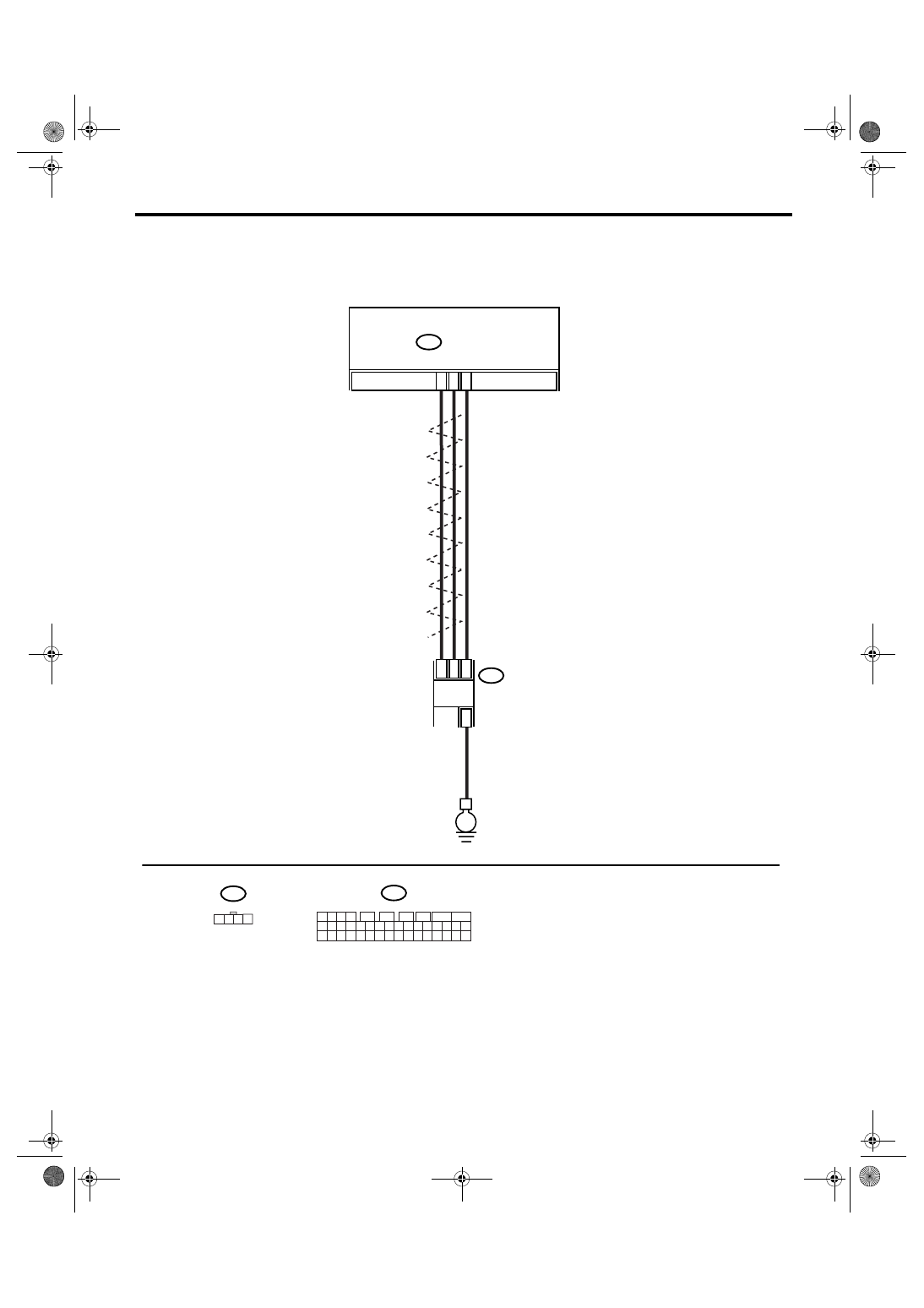
VDC00247
30
29
13
B231
E
2
4
1
3
B310
B310
VDCCM & H/U
1 2 3 4
11 12 13 14
27 28 29 30
15 16 17 18
31 32 33 34
19 20 21 22
35 36 37 38
23 24 25 26
39 40 41 42
5
6
7
8
9
10
1 2 3 4
B231
TWISTED WIRE
STEERING
ANGLE SENSOR