Subaru Legacy (2005 year). Manual - part 792
VDC(diag)-33
VEHICLE DYNAMICS CONTROL (VDC) (DIAGNOSTICS)
Warning Light Illumination Pattern
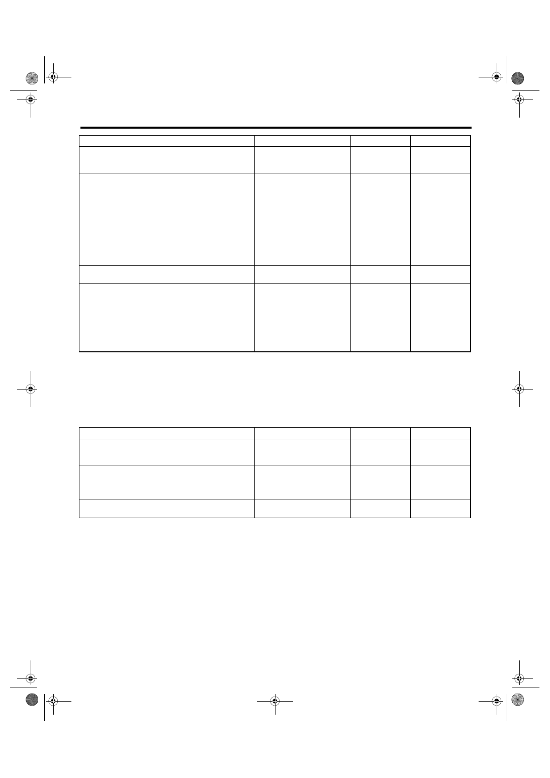
E: VDC INDICATOR LIGHT DOES NOT GO OFF
DETECTING CONDITION:
• Defective combination meter
• Defective CAN communication
TROUBLE SYMPTOM:
When starting the engine, VDC indicator light is kept ON.
Step
Check
Yes
No
1
READ DTC.
Read the DTC. <Ref. to VDC(diag)-23, Read
Diagnostic Trouble Code (DTC).>
Is DTC displayed?
Perform the diag-
nosis according to
DTC.
2
CHECK WIRING HARNESS.
1) Turn the ignition switch to OFF.
2) Disconnect the connector (B310) from
VDCCM&H/U.
3) Disconnect the connector (i10) from combi-
nation meter.
4) Measure the resistance between
VDCCM&H/U connector and combination
meter connector.
Connector & terminal
(B310) No. 35 — (i10) No. 5:
Is the resistance less than 0.5
Ω?
Repair the har-
ness connector
between
VDCCM&H/U and
combination
meter.
3
CHECK POOR CONTACT IN CONNECTOR.
Check poor contact in all connectors.
Is there poor contact?
Repair the con-
nector.
4
CHECK VDCCM.
1) Connect the connector (B310) to
VDCCM&H/U.
2) Turn the ignition switch to ON.
3) Measure the resistance between combina-
tion meter connector and chassis ground.
Connector & terminal
(i10) No. 5 — Chassis ground:
Is the resistance less than 0.5
Ω?
Check the combi-
nation meter.
Replace the
VDCCM&H/U.
Step
Check
Yes
No
1
READ DTC.
Read the DTC. <Ref. to VDC(diag)-23, Read
Diagnostic Trouble Code (DTC).>
Is DTC displayed?
Perform the diag-
nosis according to
DTC.
2
CHECK LAN SYSTEM.
Perform the diagnosis for LAN system. <Ref. to
LAN(diag)-24, OPERATION, Read Diagnostic
Trouble Code (DTC).>
Is there any fault in LAN sys-
tem?
Perform the diag-
nosis according to
DTC for LAN sys-
tem.
3
CHECK COMBINATION METER.
Check the combination meter.
Is combination meter OK?
Replace the
VDCCM&H/U.
Repair the combi-
nation meter.