Subaru Legacy (2005 year). Manual - part 757


  Index      Subaru     Subaru Legacy - service repair manual 2005 year


Search            


Content   ..  755  756  757  758   ..


Subaru Legacy (2005 year). Manual - part 757


ABS-13

ABS

Front ABS Wheel Speed Sensor

4. Front ABS Wheel Speed Sen-

sor

A: REMOVAL

1) Disconnect the ground cable from battery.
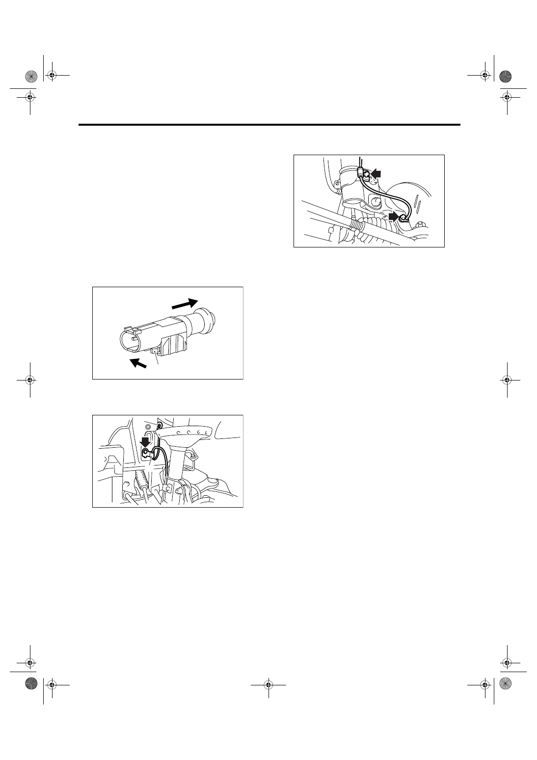
2) Disconnect the ABS wheel speed sensor con-
nector located next to the front strut mounting
house in engine compartment.
3) Separate the sensor connector and vehicle se-
curing clip. Apply force in the direction of (2) to un-
lock the pawl, and then slide the connector in the
direction of (3). Pull out the connector to the tire
side from grommet hole.

CAUTION:
Clip would break when removing the clip with-
out separating sensor connector and clip.

4) Remove the sensor harness bracket.

5) Remove the bolts which secure sensor harness
to front strut.
6) Remove the front ABS wheel speed sensor from
housing.

CAUTION:
• Be careful not to damage the sensor portion.

• Do not apply excessive force to the sensor
harness.

B: INSTALLATION

Install in the reverse order of removal.

Tightening torque:

Sensor:

7.5 N

m (0.76 kgf-m, 5.5 ft-lb)

Bracket:

33 N

m (3.4 kgf-m, 24.3 ft-lb)

CAUTION:
Be careful not to damage the sensor portion.

NOTE:
• Check the identification (mark) on the harness to
make sure that no warp exists. (RH: K1 (White),
LH: K2 (Yellow))
• Check if the harness is not pulled and does not
come in contact with the suspension or body during
steering wheel effort.

C: INSPECTION

1. INSPECTION WITH SUBARU SELECT 
MONITOR

1) Connect the Subaru Select Monitor to data link
connector.
2) Select {Current Data Display & Save}. Check if
the speed indicated on the display change in re-
sponse to the speedometer reading during acceler-
ation/deceleration when the steering wheel is in the
straight-ahead position.
3) If the speed indicated on the display does not
change, check the ABS wheel speed sensor. <Ref.
to ABS-13, ABS WHEEL SPEED SENSOR, IN-
SPECTION, Front ABS Wheel Speed Sensor.>

2. ABS WHEEL SPEED SENSOR

1) Check the pole piece of the ABS wheel speed
sensor for foreign particles or damage. If neces-
sary, clean the pole piece or replace the ABS wheel
speed sensor. 

(1) Pawl

(1) To front ABS wheel speed sensor connector

(2) Sensor harness bracket

ABS00434

(3)

(2)

(1)

ABS00386

(1)

(2)

ABS00387

ABS-14

ABS

Front ABS Wheel Speed Sensor

2) Charge a 12 V power supply to the No. 2 termi-
nal of sensor connector as shown in the figure, and
then install the resistance to No. 1 terminal. Rotate
the wheel about 2.75 km/h (2 MPH) or equivalent,
measure the voltage using oscilloscope.

Specification of output voltage:

0.7 — 1.4 V

NOTE:
Check the ABS wheel speed sensor cable for dis-
continuity. If necessary, replace with a new one.

(1) Oscilloscope

(2) ABS wheel speed sensor

ABS00388

(2)

(1)

100 

1.4 V

0.7 V

12 V

2

1

1

2

ABS-15

ABS

Rear ABS Wheel Speed Sensor

5. Rear ABS Wheel Speed Sen-

sor

A: REMOVAL

1) Disconnect the ground cable from battery.
2) Disconnect the connector from rear ABS wheel
speed sensor.

3) Remove the sensor harness bracket from rear
arm.

4) Remove the rear ABS wheel speed sensor from
rear arm.

CAUTION:
• Be careful not to damage the sensor portion.
• Do not apply excessive force to the sensor
harness.

B: INSTALLATION

Install in the reverse order of removal.

CAUTION:
Be careful not to damage the sensor portion.

Tightening torque:

Sensor:

7.5 N

m (0.76 kgf-m, 5.5 ft-lb)

Bracket:

33 N

m (3.4 kgf-m, 24.3 ft-lb)

NOTE:
Check the identification (mark) on the harness to
make sure that no warp exists. (RH:K5(White),
LH:K6(Yellow))

C: INSPECTION

1. ABS WHEEL SPEED SENSOR

<Ref. to ABS-13, ABS WHEEL SPEED SENSOR,
INSPECTION, Front ABS Wheel Speed Sensor.>

ABS00389

ABS00166

ABS00167

ABS00168

ABS00390

ABS-16

ABS

Front Magnetic Encoder

6. Front Magnetic Encoder

A: REMOVAL

Refer to “Front Hub Bearing” for removal, because
the front magnetic encoder is integrated with front
hub bearing.
<Ref. to DS-17, REMOVAL, Front Hub Unit Bear-
ing.>

B: INSTALLATION

Refer to “Front Hub Bearing” for installation, be-
cause the front magnetic encoder is integrated with
front hub bearing.
<Ref. to DS-17, INSTALLATION, Front Hub Unit
Bearing.>

C: INSPECTION

Visually check the magnetic encoder for any dam-
age. If necessary, replace with a new hub unit bear-
ing.

NOTE:
Replace the hub unit bearing with a new one if
there is any defect found on the magnetic encoder,
since the magnetic encoder is integrated with hub
unit bearing assembly.


Content   ..  755  756  757  758   ..