Subaru Legacy (2005 year). Manual - part 635
5AT(diag)-131
AUTOMATIC TRANSMISSION (DIAGNOSTICS)
Diagnostic Procedure without Diagnostic Trouble Code (DTC)
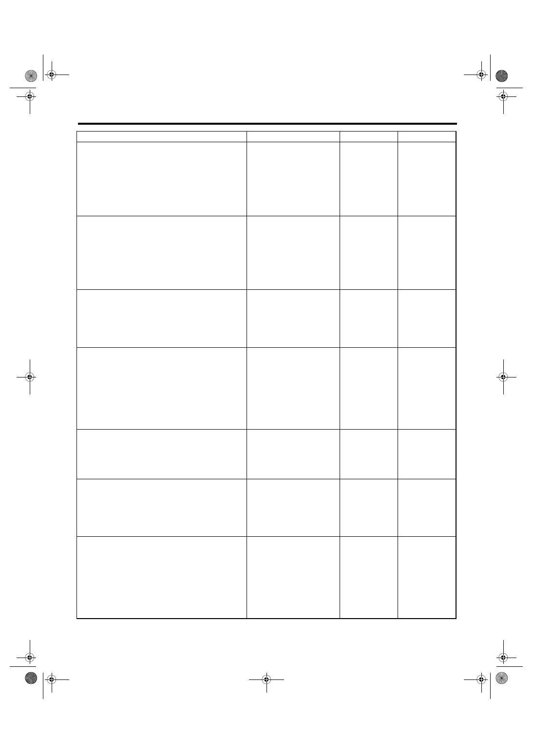
18
CHECK HARNESS CONNECTOR BETWEEN
BODY INTEGRATED MODULE AND MANU-
AL MODE SWITCH.
1) Disconnect the steering roll connector.
2) Measure the resistance of harness
between manual mode switch connector and
chassis ground.
Connector & terminal
(B116) No. 9 — Chassis ground:
Is the resistance more than 1
M
Ω?
Repair the short
circuit of harness
between manual
mode switch con-
nector and body
integrated module
connector.
19
CHECK INPUT SIGNAL TO BODY INTE-
GRATED MODULE.
1) Connect all the connectors.
2) Turn the ignition switch to ON. (engine
OFF)
3) Check the signal voltage for body inte-
grated module.
Connector & terminal
(B281) No. 25 (+) — Chassis ground (
−
):
Is the voltage more than 9 V?
Replace the body
integrated mod-
ule. <Ref. to SL-
44, Body Inte-
grated Module.>
20
CHECK INPUT SIGNAL TO BODY INTE-
GRATED MODULE.
1) Shift and hold the select lever to up side.
2) Check the signal voltage for body inte-
grated module.
Connector & terminal
(B281) No. 25 (+) — Chassis ground (
−
):
Is the voltage less than 1 V?
Replace the body
integrated mod-
ule. <Ref. to SL-
44, Body Inte-
grated Module.>
21
CHECK STEERING SHIFT SWITCH
GROUND CIRCUIT.
1) Turn the ignition switch to OFF.
2) Disconnect the connector from steering roll
connector.
3) Measure the resistance of harness
between steering roll connector and chassis
ground.
Connector & terminal
(ST4) No. 3 — Chassis ground:
Is the resistance less than 1
Ω?
Repair the open
circuit of harness
between steering
roll connector and
chassis ground.
22
CHECK STEERING SHIFT SWITCH.
Measure the resistance between steering roll
connector terminals.
Connector & terminal
(ST4) No. 3 — No. 4:
Is the resistance more than 1
M
Ω?
Replace the steer-
ing roll connector
or steering shift
switch. Or repair
the poor contact in
connector.
23
CHECK STEERING SHIFT SWITCH.
1) Press and hold the steering shift switch to +
side.
2) Measure the resistance between steering
shift switch terminals.
Connector & terminal
(ST4) No. 3 — No. 4:
Is the resistance less than 1
Ω?
Replace the steer-
ing roll connector
or steering shift
switch. Or repair
the poor contact in
connector.
24
CHECK HARNESS CONNECTOR BETWEEN
BODY INTEGRATED MODULE AND STEER-
ING ROLL CONNECTOR.
1) Disconnect the connector from body inte-
grated module.
2) Measure the resistance of harness
between body integrated module connector
and steering roll connector.
Connector & terminal
(B281) No. 15 — (B68) No. 2:
Is the resistance less than 1
Ω?
Repair the open
circuit of harness
between body inte-
grated module
connector and
steering roll con-
nector, or poor
contact in connec-
tor.
Step
Check
Yes
No