Subaru Legacy (2005 year). Manual - part 625
 

  Index      Subaru     Subaru Legacy - service repair manual 2005 year


Search            


Content   ..  623  624  625  626   ..


Subaru Legacy (2005 year). Manual - part 625


5AT(diag)-91

AUTOMATIC TRANSMISSION (DIAGNOSTICS)

Diagnostic Procedure with Diagnostic Trouble Code (DTC)

AC:DTC P0817 STARTER DISABLE CIRCUIT

DTC DETECTING CONDITION:
Open or short in P/N signal output circuit
TROUBLE SYMPTOM:
• Engine can be started on other than “P” or “N” range.
• Engine can not be started on “P” or “N” range.
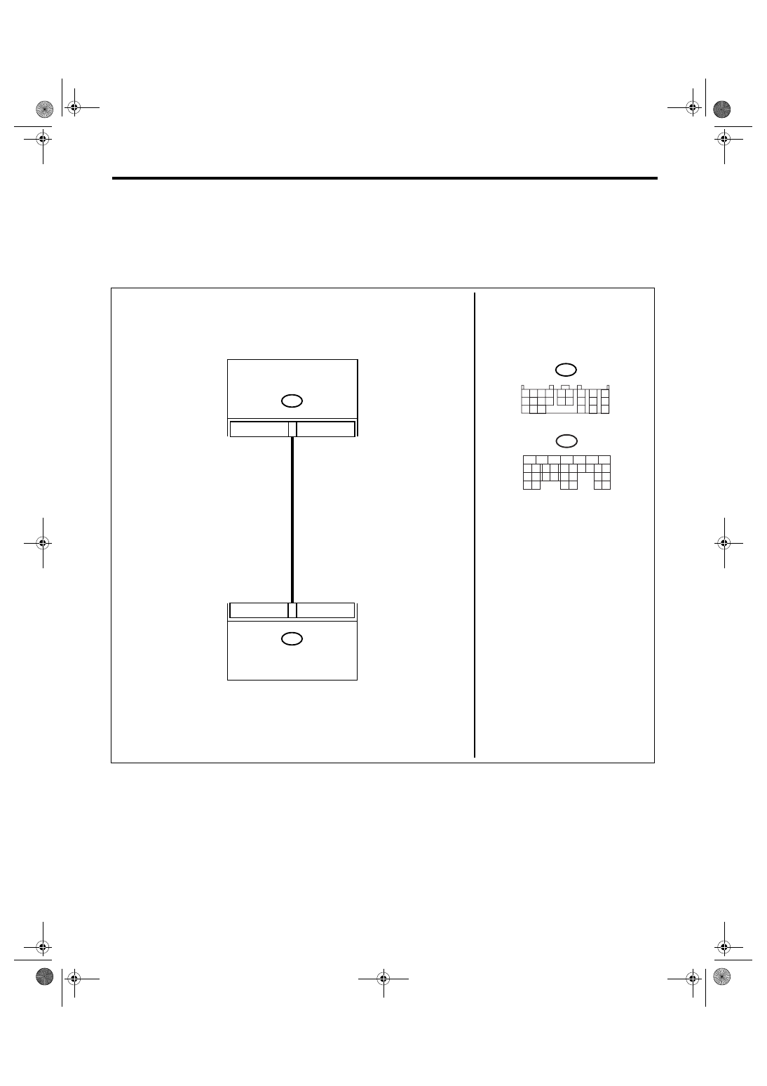
WIRING DIAGRAM:

B137

B55

AT-01632

9

19

ECM

TCM

B55

1 2 3 4

10 11 12
19 20 21

13

5 6

14 15

7

8

9

16

17

18

22

23

24

B137

5

6

7

8

2

1

9

4

3

10

22 23

11 12 13 14 15

24 25

26

16 17

18 19 20 21

27

28 29

30 31

5AT(diag)-92

AUTOMATIC TRANSMISSION (DIAGNOSTICS)

Diagnostic Procedure with Diagnostic Trouble Code (DTC)

Step

Check

Yes

No

1

CHECK DTC OF TCM.

Is DTC of Transmission Range 
Sensor Circuit (PRNDL Input) 
circuit detected?

Perform the diag-
nosis according to 
DTC.

Go to step 2.

2

CHECK ECM.

Is the communication between 
Subaru Select Monitor and 
ECM normal?

Go to step 3.

Perform the diag-
nosis according to 
DTC concerning 
ECM.

3

CHECK FUSE.
1) Turn the ignition switch to OFF.
2) Remove the fuse.

Is the fuse M/B (No. 12) blown 
out?

Replace the fuse 
M/B (No. 12). If the 
replaced fuse M/B 
(No. 12) has blown 
out easily, repair 
the short circuit of 
harness between 
fuse M/B (No. 12) 
and TCM.

Go to step 4.

4

CHECK HARNESS CONNECTOR BETWEEN 
TCM AND ECM.
1) Turn the ignition switch to OFF.
2) Disconnect the connector from TCM and 
transmission.
3) Measure the resistance of harness 
between TCM and transmission connector.

Connector & terminal

(B55) No. 19 — (B137) No. 9:

Is the resistance less than 1 
Ω?

Go to step 5.

Repair the open 
circuit of harness 
between TCM and 
transmission con-
nector, and poor 
contact in connec-
tor.

5

CHECK HARNESS CONNECTOR BETWEEN 
TCM AND ECM.
Measure the resistance of harness between 
TCM connector and chassis ground.

Connector & terminal

(B55) No. 19 — Chassis ground:

Is the resistance more than 1 
M

Ω?

Go to step 6.

Repair the short 
circuit of harness 
between transmis-
sion connector 
and chassis 
ground.

6

CHECK TCM OUTPUT SIGNAL.
1) Connect the TCM and ECM connector.
2) Turn the ignition switch to ON. (engine 
OFF)
3) Shift the select lever to “P” range.
4) Measure the voltage between TCM con-
nector and chassis ground.

Connector & terminal

(B55) No. 19 (+) — Chassis ground (

):

Is the voltage more than 10 V? Go to step 7.

Replace the TCM. 
<Ref. to 5AT-61, 
Transmission Con-
trol Module 
(TCM).>

7

CHECK TCM OUTPUT SIGNAL.
1) Shift the select lever to “D” range.
2) Measure the voltage between TCM con-
nector and chassis ground.

Connector & terminal

(B55) No. 19 (+) — Chassis ground (

):

Is the voltage less than 1 V?

Go to step 8.

Replace the TCM. 
<Ref. to 5AT-61, 
Transmission Con-
trol Module 
(TCM).>

8

CHECK POOR CONTACT.

Is there any open or poor con-
tact of connector (loosing ter-
minal, entering foreign matter, 
damaging connector body)?

Repair the poor 
contact.

Check the neutral 
position switch of 
ECM.

5AT(diag)-93

AUTOMATIC TRANSMISSION (DIAGNOSTICS)

Diagnostic Procedure with Diagnostic Trouble Code (DTC)

AD:DTC P0882 TCM POWER INPUT SIGNAL LOW

DTC DETECTING CONDITION:
Malfunction of PVIGN power supply relay or open, short circuit of PVIGN power supply circuit.
TROUBLE SYMPTOM:
Gear is not changed.
WIRING DIAGRAM:

AT-03092

8

7

10

B54

B357

TCM

B54

B357

1 2

7

8

9

5 6

3 4

10 11 12
19 20 21

13

14 15

16

17

18

22

23

24

MAIN SBF

SBF-8

No.12

E

3

2

4

1

IGNITION
SWITCH

BATTERY

1 2

3
4

1 2

3
4

5AT(diag)-94

AUTOMATIC TRANSMISSION (DIAGNOSTICS)

Diagnostic Procedure with Diagnostic Trouble Code (DTC)

Step

Check

Yes

No

1

CHECK FUSE.
1) Turn the ignition switch to OFF.
2) Remove the MAIN SBF, SBF 8 and fuse 
(No. 12), and then check those are not blown 
out.

Is the fuse blown out?

Replace the fuse. 
If the replaced 
fuse has blown out 
easily, repair the 
short circuit of har-
ness of each fuse.

Go to step 2.

2

CHECK INPUT VOLTAGE FOR PVIGN RE-
LAY.
Measure the voltage between PVIGN relay and 
chassis ground.

Connector & terminal

(B357) No. 2 (+) — Chassis ground (

):

(B357) No. 3 (+) — Chassis ground (

):

Is the voltage 10 — 13 V?

Go to step 3.

Repair the open 
circuit of harness 
between fuse (No. 
12) and PVIGN 
relay.

3

CHECK HARNESS BETWEEN PVIGN RE-
LAY OF TCM.
Measure the resistance between TCM connec-
tor and PVIGN relay connector.

Connector & terminal

(B54) No. 10 — (B357) No. 1:
(B54) No. 7 — (B357) No. 4:
(B54) No. 8 — (B357) No. 4:

Is the resistance less than 1 
Ω?

Go to step 4.

Repair the open 
circuit of harness.

4

CHECK PVIGN POWER SUPPLY CIRCUIT.
1) Turn the ignition switch to ON. (engine 
OFF)
2) Measure the voltage between TCM con-
nector and chassis ground.

Connector & terminal

(B54) No. 7 (+) — Chassis ground (

):

(B54) No. 8 (+) — Chassis ground (

):

Is the voltage 10 — 13 V?

Temporary poor 
contact. Recheck 
the harness 
between TCM and 
relay. (Lightly 
move the harness 
and check that the 
open or short cir-
cuit is not 
occurred.)

Go to step 5.

5

CHECK PVIGN RELAY OUTPUT OF TCM.
Measure the voltage between TCM connector 
and chassis ground.

Connector & terminal

(B54) No. 10 (+) — Chassis ground (

):

Is the voltage less than 1.5 V? Replace the 

PVIGN relay.

Replace the TCM. 
<Ref. to 5AT-61, 
Transmission Con-
trol Module 
(TCM).>


Content   ..  623  624  625  626   ..