Subaru Legacy (2005 year). Manual - part 619
5AT(diag)-67
AUTOMATIC TRANSMISSION (DIAGNOSTICS)
Diagnostic Procedure with Diagnostic Trouble Code (DTC)
T: DTC P0756 SHIFT SOLENOID “B” PERFORMANCE OR STUCK OFF
DTC DETECTING CONDITION:
Output signal value of input clutch solenoid and oil pressure does not match.
TROUBLE SYMPTOM:
Locked to 4th gear.
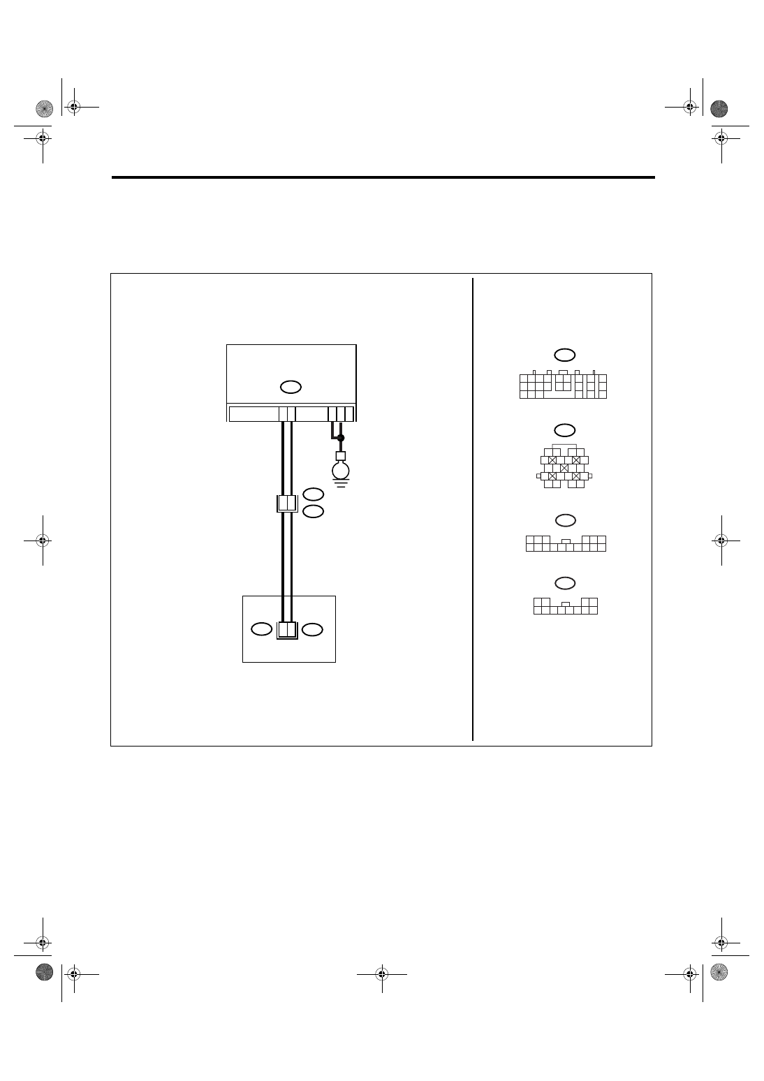
WIRING DIAGRAM:
AT-03185
B54
18
B11
TCM
B54
B11
1 2
5
6 7
8
13
14 15
16
9 10
11 12
3 4
17 18
19 20
TRANSMISSION
1 2
7
8
9
5 6
3 4
10 11 12
19 20 21
13
14 15
16
17
18
22
23
24
T4
T11
1 2
5
8
6
9 10 11
3 4
12
T11
7
E
5
14
8
8
18
11
6
T10
1 2 3
6
8 9 10 11 12 13 14
4 5
15 16
T10
7