Subaru Legacy (2005 year). Manual - part 565
4AT(diag)-97
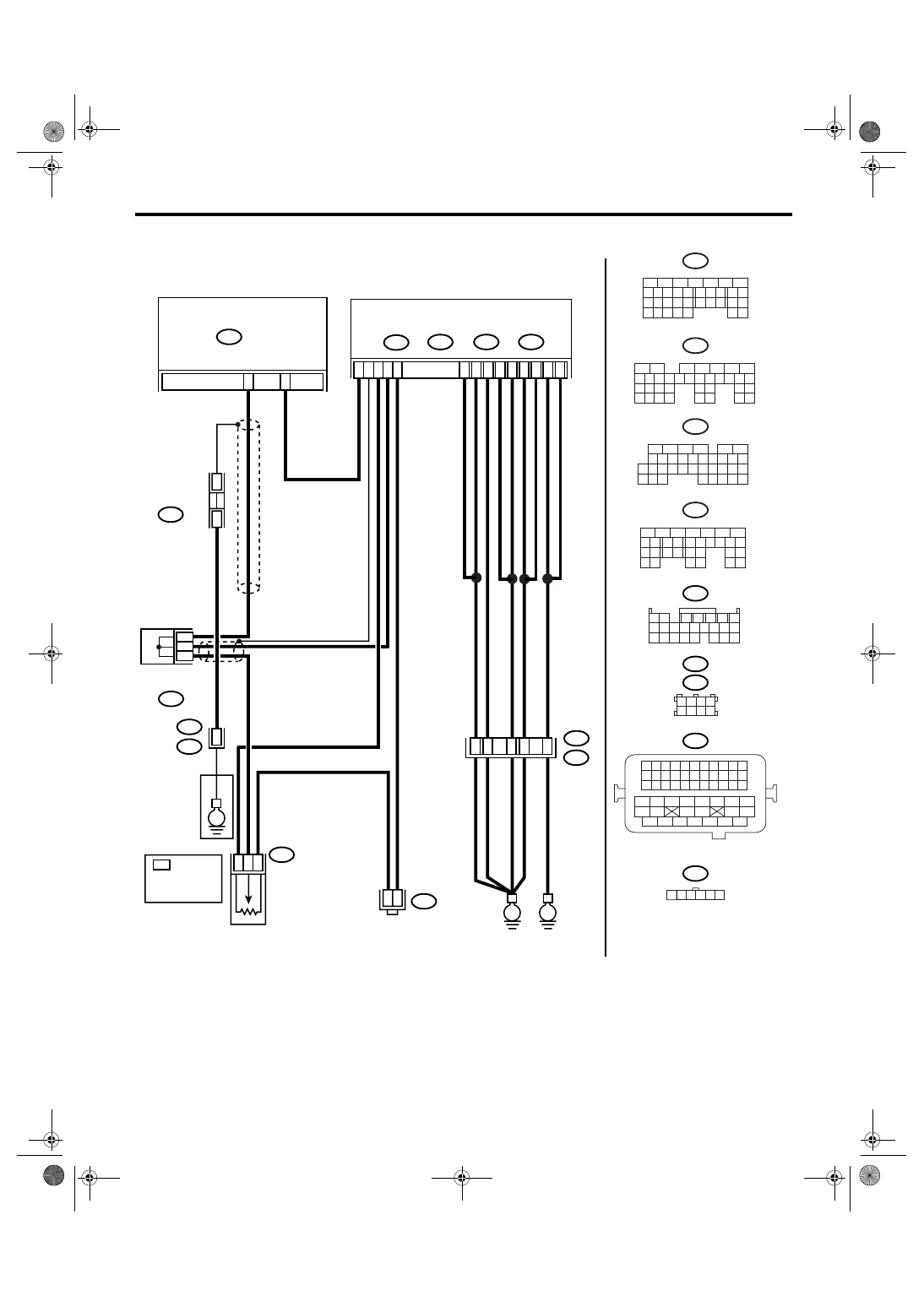
AUTOMATIC TRANSMISSION (DIAGNOSTICS)
Diagnostic Procedure with Diagnostic Trouble Code (DTC)
• 2.0 L RHD and 2.5 L KA model
AT-01895
2 3 4
1
5 6
*
TERMINAL NO.
RANDOM
ARRANGEMENT
B54
B21
1 2
7
8 9
5
6
3
4
10 11 12
19 20 21
13 14 15 16
17 18
22 23 24
B315
B183
B21
B134
B183
B54
TCM
A:
B135
B:
B136
C:
ECM
B137
D:
E2
52
35
36
1
2
6
19
C17
D30
C18
B6
B5
A7
A2
C6
C5
D1
E
E
*
*
JOINT CONNECTOR
ACCELERATOR PEDAL POSITION SENSOR
B315
C2
34
B137
5
6
7
8
2
1
9
4
3
10
22 23
11 12 13 14 15
24 25
26
16 17
18 19 20 21
27
28 29
30 31
B134
5
6
7
8
2
1
9
4
3
10
24
22 23
25
11 12 13 14 15
26 27
28
16 17
18 19 20 21
33 34
29
32
30 31
B136
5
6
7 8
2
1
9
4
3
10
24
22 23
25
11 12 13 14 15
26 27
28
16
17 18 19 20 21
33 34
29
32
30
31
35
B135
5
6
7
8
2
1
9
4
3
10
24
22 23
25
11 12 13 14 15
26 27
28
16 17 18 19
20 21
29 30 31
32 33
34 35
1 2 3 4
5 6 7 8
1 2 3 4
12 13 14 15
5 6 7 8
16 17 18 19
9 10 11
20 21 22
23 24 25 26 27 28 29 30 31 32 33
35
34
37
36
39
38
41
40
43
42
44
45
47
46
49
48
51
50
53
52
54
A:
B:
C:
D:
B122
B122
JOINT
CONNECTOR
D18
D19
10
*
*
*
C1
6
7
B53
JOINT
CONNECTOR
19
B11
T4
37
E
: