Subaru Legacy (2005 year). Manual - part 561
 

  Index      Subaru     Subaru Legacy - service repair manual 2005 year


Search            


Content   ..  559  560  561  562   ..


Subaru Legacy (2005 year). Manual - part 561


4AT(diag)-81

AUTOMATIC TRANSMISSION (DIAGNOSTICS)

Diagnostic Procedure with Diagnostic Trouble Code (DTC)

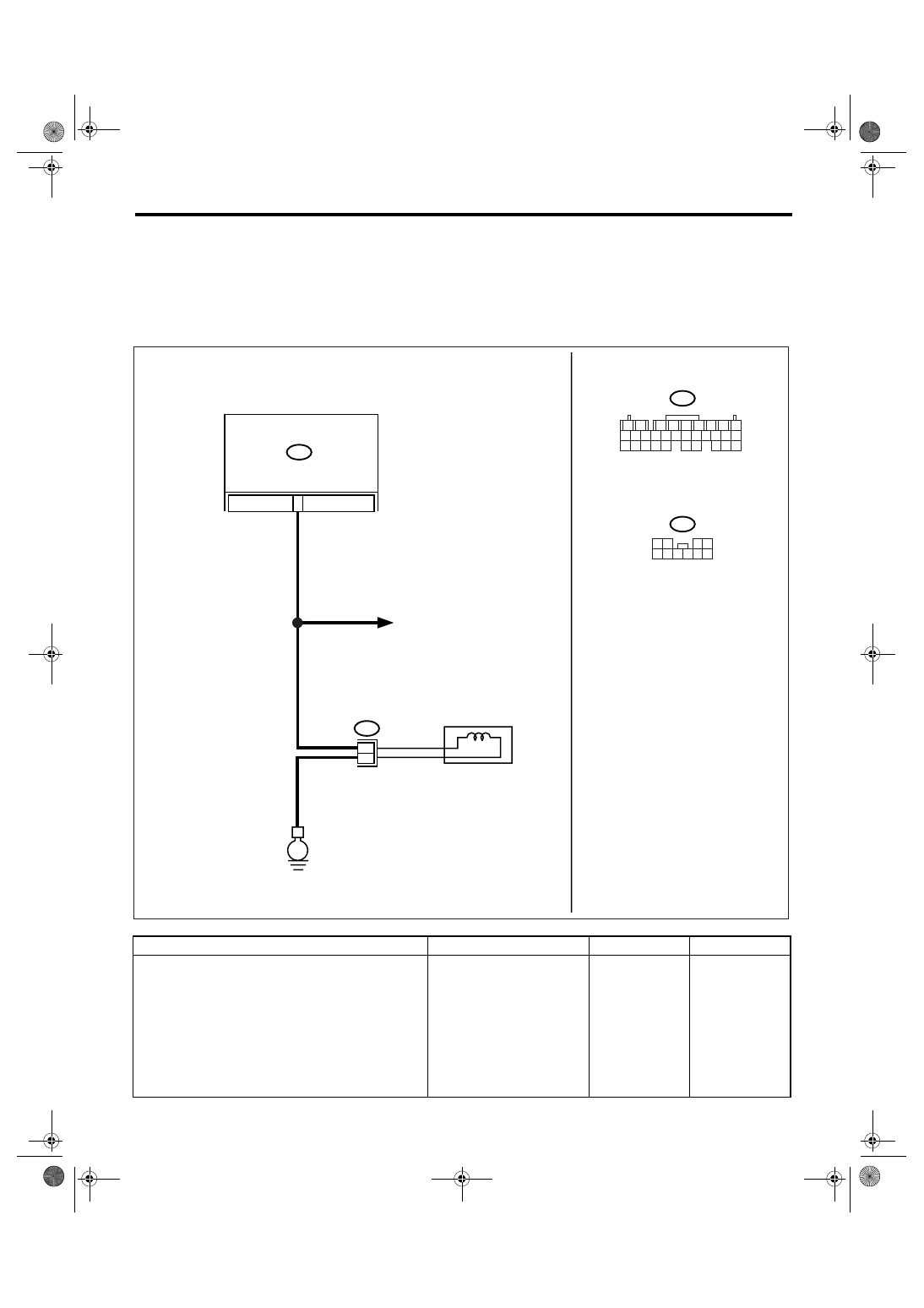
U: DTC P0801 REVERSE INHIBIT CONTROL CIRCUIT

DTC DETECTING CONDITION:
Shift lock solenoid malfunction, open or short reverse inhibitor control circuit
TROUBLE SYMPTOM:
• Gear is shifted from “N” range to “R” range during driving at 20 km/h (12 MPH) or more.
• Gear cannot be shifted from “N” range to “R” range.
WIRING DIAGRAM:

Step

Check

Yes

No

1

CHECK HARNESS CONNECTOR BETWEEN 
TCM AND SHIFT LOCK SOLENOID.
1) Turn the ignition switch to OFF.
2) Disconnect the connector from TCM and 
shift lock solenoid.
3) Measure the resistance of harness 
between TCM and shift lock solenoid connec-
tor.

Connector & terminal

(B55) No. 18 — (B116) No. 3:

Is the resistance less than 1 
Ω?

Go to step 2.

Repair the open 
circuit of harness 
between TCM and 
shift lock solenoid 
connector.

AT-01893

TCM

18

B55

E

B116

B55

B116

3
4

1

2

7

8

9

5

6

3

4

10 11 12

19 20 21
29 30 31

13 14 15 16 17

27 28

18

22 23 24 25 26

2

3

6 7 8 9

1
5

4

10

BODY INTEGRATED MODULE

SHIFT LOCK
SOLENOID

4AT(diag)-82

AUTOMATIC TRANSMISSION (DIAGNOSTICS)

Diagnostic Procedure with Diagnostic Trouble Code (DTC)

2

CHECK HARNESS CONNECTOR BETWEEN 
TCM AND SHIFT LOCK SOLENOID.
Measure the resistance of harness between 
TCM and chassis ground.

Connector & terminal

(B55) No. 18 — Chassis ground:

Is the resistance more than 1 
M

Ω?

Go to step 3.

Repair the short 
circuit of harness 
between TCM and 
shift lock solenoid 
connector.

3

CHECK HARNESS BETWEEN SHIFT LOCK 
SOLENOID AND CHASSIS GROUND TERMI-
NAL.
Measure the resistance of harness between 
shift lock solenoid and chassis ground.

Connector & terminal

(B116) No. 4 — Chassis ground:

Is the resistance less than 1 
Ω?

Go to step 4.

Repair the open 
circuit of harness 
between chassis 
ground and shift 
lock solenoid con-
nector.

4

CHECK SHIFT LOCK SOLENOID.
Measure the resistance of shift lock solenoid 
terminals.

Connector & terminal

(B116) No. 3 — No. 4:

Is the resistance 12 — 18 

Ω?

Go to step 5.

Replace the shift 
lock solenoid.

5

CHECK OUTPUT SIGNAL OF TCM.
1) Connect all the connectors.
2) Turn the ignition switch to ON.
3) Shift the select lever to “D” range.
4) Measure the voltage between TCM and 
chassis ground.

Connector & terminal

(B55) No. 18 (+) — Chassis ground (

):

Is the voltage more than 10.5 
V?

Go to step 6.

Go to step 7.

6

CHECK OUTPUT SIGNAL OF TCM.
1) Lift-up the vehicle.

NOTE:

Raise all wheels off floor.

2) Start the engine.
3) Shift the select lever to “D” range and 
slowly increase vehicle speed to 20 km/h (12 
MPH).

NOTE:

The speed difference between front and rear
wheels may light the ABS warning light or VDC
warning light, but this indicates no malfunction.
When AT control diagnosis is finished, perform
the ABS memory clearance procedure or VDC
memory clearance procedure of on-board diag-
nostics system. <Ref. to ABS(diag)-26, Clear
Memory Mode.> <Ref. to VDC(diag)-25, Clear
Memory Mode.>

4) Measure the voltage between TCM and 
chassis ground.

Connector & terminal

(B55) No. 18 (+) — Chassis ground (

):

Is the voltage less than 1 V?

Even if the SPORT 
indicator light is 
blinking, the cir-
cuit has returned 
to normal condi-
tion at this time. A 
temporary poor 
contact of connec-
tor or harness may 
be the cause. 
Repair the har-
ness or connector 
in reverse inhibitor 
control circuit.

Go to step 7.

7

CHECK POOR CONTACT.

Is there poor contact in the 
reverse inhibitor control circuit?

Repair the poor 
contact.

Replace the TCM. 
<Ref. to 4AT-66, 
Transmission Con-
trol Module 
(TCM).>

Step

Check

Yes

No

4AT(diag)-83

AUTOMATIC TRANSMISSION (DIAGNOSTICS)

Diagnostic Procedure with Diagnostic Trouble Code (DTC)

V: DTC P1706 AT VEHICLE SPEED SENSOR CIRCUIT MALFUNCTION (REAR 

WHEEL)

DTC DETECTING CONDITION:
Input signal circuit of TCM is open or shorted.
TROUBLE SYMPTOM:
No lock-up or occurring tight corner braking phenomenon.
WIRING DIAGRAM:

AT-03161

23

24

B11

AT1

T4

9

17

13

3

1

2

B54

TCM

BATTERY

IGNITION 
SWITCH

REAR VEHICLE
SPEED SENSOR

E

MAIN SBF

SBF-6

1 2 3

B11

AT1

1

2

3 4

5

6 7

8

9

13

14 15

20

19

17

16

10

11 12

18

B54

1 2

7

8 9

5

6

3

4

10 11 12
19 20 21

13 14 15 16

17 18

22 23 24

No.12

4AT(diag)-84

AUTOMATIC TRANSMISSION (DIAGNOSTICS)

Diagnostic Procedure with Diagnostic Trouble Code (DTC)

Step

Check

Yes

No

1

CHECK IGNITION POWER SUPPLY CIR-
CUIT.
1) Turn the ignition switch to OFF.
2) Disconnect the connector from rear vehicle 
speed sensor.
Turn the ignition switch to ON.
3) Measure the ignition power supply voltage 
between rear vehicle speed sensor connector 
and transmission ground.

Connector & terminal

(AT1) No. 3 (+) — Transmission ground (

):

Is the voltage more than 10 V? Go to step 2.

Check harness 
between rear vehi-
cle speed sensor 
and battery for 
open circuit, short 
or poor contact. 
Repair the har-
ness if required.

2

CHECK HARNESS CONNECTOR BETWEEN 
TCM AND TRANSMISSION.
1) Turn the ignition switch to OFF.
2) Measure the resistance of harness 
between TCM connector and rear vehicle 
speed sensor connector.

Connector & terminal

(B54) No. 23 — (AT1) No. 1:

Is the resistance less than 1 
Ω?

Go to step 3.

Repair the open 
circuit or poor con-
tact of connector in 
harness between 
TCM and rear 
vehicle speed sen-
sor connector.

3

CHECK HARNESS CONNECTOR BETWEEN 
TCM AND TRANSMISSION.
Measure the resistance of harness between 
TCM connector and rear vehicle speed sensor 
connector.

Connector & terminal

(B54) No. 24 — (AT1) No. 2:

Is the resistance less than 1 
Ω?

Go to step 4.

Repair the open 
circuit or poor con-
tact of connector in 
harness between 
TCM and rear 
vehicle speed sen-
sor connector.

4

CHECK HARNESS CONNECTOR BETWEEN 
TCM AND TRANSMISSION.
Measure the resistance of harness between 
TCM connector and chassis ground.

Connector & terminal

(B54) No. 23 — Chassis ground:

Is the resistance more than 1 
M

Ω?

Go to step 5.

Repair the short 
circuit of harness 
between TCM and 
rear vehicle speed 
sensor connector.

5

CHECK HARNESS CONNECTOR BETWEEN 
TCM AND TRANSMISSION.
Measure the resistance of harness between 
TCM connector and chassis ground.

Connector & terminal

(B54) No. 24 — Chassis ground:

Is the resistance more than 1 
M

Ω?

Go to step 6.

Repair the short 
circuit of harness 
between TCM and 
rear vehicle speed 
sensor connector.


Content   ..  559  560  561  562   ..