Subaru Legacy (2005 year). Manual - part 551
4AT(diag)-41
AUTOMATIC TRANSMISSION (DIAGNOSTICS)
Diagnostic Procedure with Diagnostic Trouble Code (DTC)
B: DTC P0712 TRANSMISSION FLUID TEMPERATURE SENSOR CIRCUIT LOW
INPUT
DTC DETECTING CONDITION:
Input signal circuit of TCM to ATF temperature sensor is open or shorted.
TROUBLE SYMPTOM:
Excessive shift shock
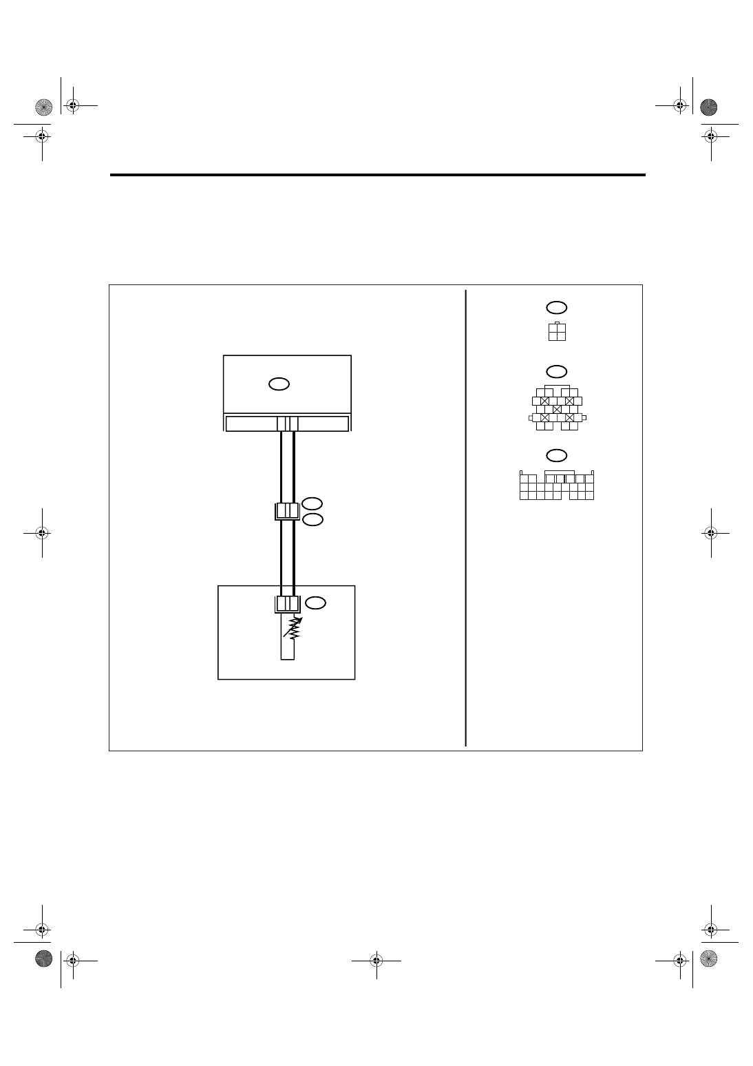
WIRING DIAGRAM:
AT-02227
B11
B54
AT2
1
2
3 4
5
6 7
8
9
13
14 15
20
19
17
16
10
11 12
18
21
9
15
11
3
1
B54
B11
AT2
T4
TCM
3 4
1 2
1 2
7
8 9
5
6
3
4
10 11 12
19 20 21
13 14 15 16
17 18
22 23 24
ATF TEMPERATURE
SENSOR
TRANSMISSION