Subaru Legacy (2005 year). Manual - part 535


  Index      Subaru     Subaru Legacy - service repair manual 2005 year


Search            


Content   ..  533  534  535  536   ..


Subaru Legacy (2005 year). Manual - part 535


4AT-121

AUTOMATIC TRANSMISSION

AT Main Case

41.AT Main Case

A: REMOVAL

1) Remove the transmission assembly from vehi-
cle. <Ref. to 4AT-39, REMOVAL, Automatic Trans-
mission Assembly.>
2) Pull out the torque converter clutch assembly.
<Ref. to 4AT-81, REMOVAL, Torque Converter
Clutch Assembly.>
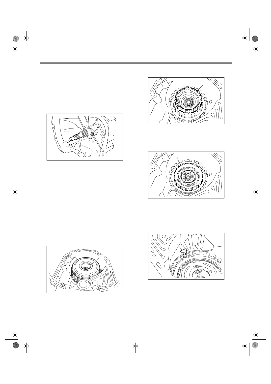
3) Remove the input shaft.

4) Lift up the lever on rear side of transmission har-
ness connector, and then disconnect it from the
stay.
5) Disconnect the inhibitor switch connector from
stay.
6) Disconnect the air breather hose.
7) Remove the oil charge pipe. <Ref. to 4AT-80,
REMOVAL, Oil Charge Pipe.>
8) Remove the oil cooler inlet and outlet pipes.
<Ref. to 4AT-68, REMOVAL, ATF Cooler Pipe and
Hose.>
9) Separate the converter case and transmission
case. <Ref. to 4AT-102, REMOVAL, Converter
Case.>
10) Remove the oil pump housing.
<Ref. to 4AT-104, REMOVAL, Oil Pump Housing.>
11) Take out the high clutch, thrust needle bearing
and reverse clutch assembly.

12) Take out the high clutch hub and thrust bear-
ing.

13) Take out the front sun gear and thrust needle
bearing.

14) Pull out the leaf spring without folding.

NOTE:
Remove it while pressing down lower leaf spring.

(A) High clutch and reverse clutch ASSY

(B) Thrust needle bearing

AT-00114

AT-00232

(B)

(A)

(A) High clutch hub

(B) Thrust needle bearing

(A) Front sun gear

(B) Thrust needle bearing

(A) Leaf spring

(B) Retaining plate

AT-00233

(A)

(B)

AT-00251

(A)

(B)

AT-00252

(A)

(B)

4AT-122

AUTOMATIC TRANSMISSION

AT Main Case

15) Remove the snap ring and thrust needle bear-
ing.

16) Take out the retaining plate, drive plate and
driven plate of 2-4 brake.

17) Take out the thrust needle bearing, planetary
gear assembly and low clutch assembly.

18) Remove the 2-4 brake seal.

19) Remove the snap ring.

20) Take out the 2-4 brake return spring.

21) Remove the 2-4 brake piston and piston retain-
er without damaging.

(A) Snap ring

(B) Thrust needle bearing

AT-00253

(A)

(B)

AT-00254

AT-00255

AT-02215

(A) Snap ring

(B) 2-4 brake piston

(A) 2-4 brake piston

(B) 2-4 brake piston retainer

AT-00285

(B)

(A)

AT-00286

AT-00287

(A)

(B)

4AT-123

AUTOMATIC TRANSMISSION

AT Main Case

22) Pull out the leaf spring without folding.

23) Remove the snap ring.

24) Take out the retaining plate, drive plate, driven
plate and dish plate.

25) Turn the transmission case upside down, and
then take out the socket bolts while holding the
one-way clutch inner race with hand.

26) Remove the spring retainer.

27) Take out the return spring.

28) Apply compressed air.

29) Take out the low & reverse piston.

(A) Leaf spring

(A) Snap ring

AT-00293

(A)

AT-00294

( A )

AT-00295

AT-00296

AT-00302

AT-00301

AT-00297

AT-00300

4AT-124

AUTOMATIC TRANSMISSION

AT Main Case

B: INSTALLATION

1) Install the low & reverse brake piston.

NOTE:
• Be careful not to damage the lip seal.
• Apply ATF to lips.

2) Install the return spring.

3) Install the spring retainer.

4) Install the one-way clutch inner race, spring re-
tainer and return spring.

5) Tighten the socket bolts evenly from the rear
side of transmission case.

Tightening torque:

25 N

m (2.5 kgf-m, 18.4 ft-lb)

6) Place the front side of transmission body up.
7) Install the thrust needle bearing.
8) Place the dish plate, driven plate, drive plate and
retaining plate neatly in this order on surface table.
9) Set the dial gauge to clutch, and read its scale.

NOTE:
The value, which is read in the gauge at this time, is
zero point.
10) Scale and record the weight “Z” of a flat board
which will be put on retaining plate.

NOTE:
• Use a stiff board which does not bend against
load as a flat board to be put on retaining plate.
• Use a flat board of its weight less than 8.5 kg
(18.7 lb).
11) Put the flat board weighed on retaining plate.

12) Using the following formula, calculate “N” indi-
cated on the push/pull gauge.
N = 83 N (8.5 kgf, 18.7 lbf) 

− Z

N: Value indicated on push/pull gauge
83 N (8.5 kgf, 18.7 lbf): Load applied to clutch plate
Z: Flat board weight

AT-00300

AT-00301

AT-00302

AT-00296

AT-01720


Content   ..  533  534  535  536   ..