Subaru Legacy (2005 year). Manual - part 477
EN(H6DO)(diag)-221
ENGINE (DIAGNOSTICS)
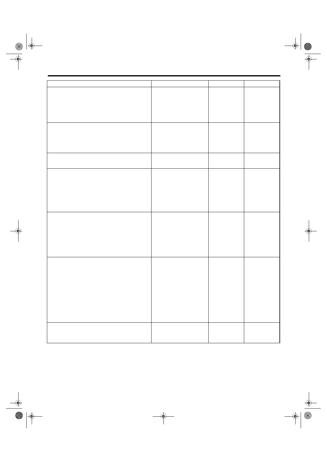
Diagnostic Procedure with Diagnostic Trouble Code (DTC)
Step
Check
Yes
No
1
CHECK INPUT SIGNAL OF ECM.
1) Turn the ignition switch to ON.
2) Place the shift lever except in neutral.
3) Measure the voltage between ECM and
chassis ground.
Connector & terminal
(B137) No. 9 (+) — Chassis ground (
−
):
Is the voltage more than 10 V? Go to step 2.
2
CHECK INPUT SIGNAL OF ECM.
1) Place the shift lever in neutral.
2) Measure the voltage between ECM and
chassis ground.
Connector & terminal
(B137) No. 9 (+) — Chassis ground (
−
):
Is the voltage less than 1 V?
3
CHECK POOR CONTACT.
Check poor contact in ECM connector.
Is there poor contact in ECM
connector?
Repair the poor
contact in ECM
connector.
Replace the ECM.
4
CHECK NEUTRAL POSITION SWITCH.
1) Place the shift lever in neutral.
2) Measure the resistance between transmis-
sion harness connector terminals.
Connector & terminal
LHD model
(T2) No. 1 — No. 3:
LHD model
(T9) No. 1 — No. 3:
Is the resistance less than 1
Ω?
Repair the open
circuit in transmis-
sion harness or
replace the neu-
tral position switch.
5
CHECK HARNESS BETWEEN ECM AND
NEUTRAL POSITION SWITCH CONNEC-
TOR.
1) Disconnect the connector from ECM.
2) Measure the resistance of harness
between ECM and transmission harness con-
nector.
Connector & terminal
(B137) No. 9 — (B128) No. 1:
Is the resistance less than 1
Ω?
Repair the open
circuit of harness
between ECM and
transmission har-
ness connector.
6
CHECK HARNESS BETWEEN ECM AND
NEUTRAL POSITION SWITCH CONNEC-
TOR.
Measure the resistance of harness between
transmission harness connector and engine
ground.
Connector & terminal
(B128) No. 3 — Engine ground:
Is the resistance less than 5
Ω?
Repair the har-
ness and connec-
tor.
NOTE:
In this case, repair
the following:
• Open circuit of
harness between
transmission har-
ness connector
and engine ground
• Poor contact in
coupling connector
7
CHECK POOR CONTACT.
Check poor contact in transmission harness
connector.
Is there poor contact in trans-
mission harness connector?
Repair poor con-
tact in transmis-
sion harness
connector.
Replace the ECM.