Subaru Legacy (2005 year). Manual - part 436
EN(H6DO)(diag)-57
ENGINE (DIAGNOSTICS)
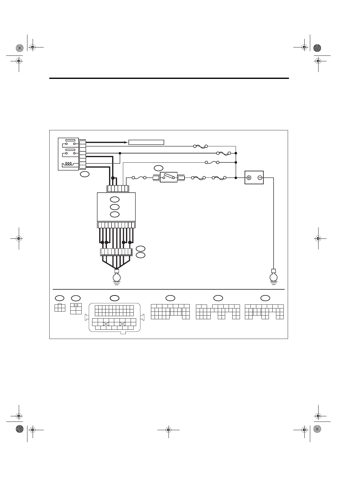
Diagnostics for Engine Starting Failure
C: CHECK POWER SUPPLY AND GROUND LINE OF ENGINE CONTROL MOD-
ULE (ECM)
CAUTION:
After repair or replacement of faulty parts, conduct Clear Memory Mode <Ref. to EN(H6DO)(diag)-41,
OPERATION, Clear Memory Mode.> and Inspection Mode <Ref. to EN(H6DO)(diag)-34, PROCEDURE,
Inspection Mode.>.
WIRING DIAGRAM:
EN-03490
BATTERY
IGNITION
SWITCH
MAIN RELAY
SBF-6
MAIN SBF
SBF-7
B72
B6
B5
D16
A6
D2
A7
B12
D3
D7
D1
B19
D14
No.12
B47
E2
B21
ECM
E
E
3
6
B134
B135
A:
D: B137
B:
B4
52
37
36
34
12
3
4
1
2
5
6
B47
No.13
B1
35
B134
5
6
7
8
2
1
9
4
3
10
24
22 23
25
11 12 13 14 15
26 27
28
16 17
18 19 20 21
33 34
29
32
30 31
B135
5
6
7
8
2
1
9
4
3
10
24
22 23
25
11 12 13 14 15
26 27
28
16 17 18 19
20 21
29 30 31
32 33
34 35
B137
5
6
7
8
2
1
9
4
3
10
22 23
11 12 13 14 15
24 25
26
16 17
18 19 20 21
27
28 29
30 31
B21
1 2 3 4
12 13 14 15
5 6 7 8
16 17 18 19
9 10 11
20 21 22
23 24 25 26 27 28 29 30 31 32 33
35
34
37
36
39
38
41
40
43
42
44
45
47
46
49
48
51
50
53
52
54
B72
1
3
4 5 6
2
A:
B:
D:
SBF-5
A4
A5
54
3
5
6
4
1
2
TO OXYGEN SENSOR