Subaru Legacy (2005 year). Manual - part 397


  Index      Subaru     Subaru Legacy - service repair manual 2005 year


Search            


Content   ..  395  396  397  398   ..


Subaru Legacy (2005 year). Manual - part 397


ME(H6DO)-63

MECHANICAL

Cylinder Head

(3) Turn the cylinder head upside down and
place the ST as shown in the figure.

ST

18251AA040

VALVE GUIDE ADJUSTER

(4) Before installing a new valve guide, make
sure that neither scratches nor damages exist
on the inside surface of the valve guide holes in
cylinder head.
(5) Put a new valve guide, coated with sufficient
oil, in cylinder, and insert the ST1 into valve
guide. Press in until the valve guide upper end is
flush with the upper surface of ST2.

ST1

499765700

VALVE GUIDE REMOVER

ST2

18251AA040 VALVE GUIDE ADJUSTER

(6) Check the valve guide protrusion.

Valve guide protrusion L:

11.4 — 11.8 mm (0.449 — 0.465 in)

(7) Ream the inside of valve guide using ST.
Put the reamer in valve guide, and rotate the
reamer slowly clockwise while pushing it lightly.
Bring the reamer back while rotating it clock-
wise. After reaming, clean the valve guide to re-
move chips.

ST

499765900

VALVE GUIDE REAMER

NOTE:
• Apply engine oil to the reamer when reaming.
• If the inner surface of the valve guide is torn, the
edge of the reamer should be slightly ground with
an oil stone.
• If the inner surface of the valve guide becomes
lustrous and the reamer does not chip, use a new
reamer or remedy the reamer.

(8) Recheck the contact condition between
valve and valve seat after replacing the valve
guide.

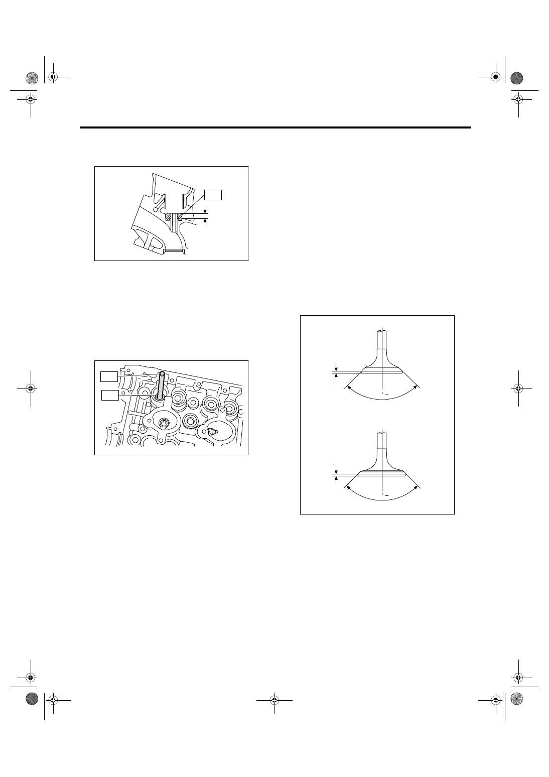
4. INTAKE AND EXHAUST VALVE

1) Inspect the flange and stem of valve, and re-
place if damaged, worn or deformed, or if “H” ex-
ceeds the standard or offset wearing is emitted.

H:

Intake (A)

Standard: 1.0 mm (0.039 in)

Exhaust (B)

Standard: 1.2 mm (0.047 in)

Valve overall length:

Intake (A)

99.7 mm (3.925 in)

Exhaust (B)

105.2 mm (4.142 in)

2) Put a small amount of grinding compound on the
seat surface, and lap the valve and seat surface.
Install a new intake valve oil seal after lapping.

ME-00757

ST

L

ME-00130

ST1

ST2

ME-02096

H

H

(B)

(A)

90    0

+1

90    0

+1

ME(H6DO)-64

MECHANICAL

Cylinder Head

5. VALVE SPRING

1) Check the valve springs for damage, free length,
and tension. Replace the valve spring if it is not
within the standard presented in the table.

2) To measure the squareness of the valve spring,
stand the spring on a surface plate and measure its
deflection at the top of spring using a try square.

6. INTAKE AND EXHAUST VALVE OIL 
SEAL

In the following case, pinch and remove the oil seal
from valve using pliers, and then replace it with a
new one.
• When the lip is damaged.
• When the spring is out of the specified position.
• When readjusting the surfaces of intake valve
and valve sheet.
• When replacing the intake valve guide.
1) Set the cylinder head on ST1.
2) Press-fit the oil seal to the specified dimension
indicated in the figure using ST2.
ST1

18250AA010 CYLINDER HEAD TABLE

ST2

499585500

VALVE OIL SEAL GUIDE

NOTE:
• Apply engine oil to oil seal before force-fitting.

• When press-fitting the oil seal, do not use a ham-
mer or strike in.

7. VALVE LIFTER

1) Check the valve lifter visually.
2) Measure the outer diameter of valve lifter.

Outer diameter:

32.959 — 32.975 mm (1.2976 — 1.2982 in)

3) Measure the inner diameter of valve lifter hole of
cylinder head.

Inner diameter:

32.994 — 33.016 mm (1.2990 — 1.2998 in)

NOTE:
If difference between outer diameter of valve lifter
and inner diameter of valve lifter hole is out of the
standard or offset wearing is emitted, replace the
cylinder head.

Standard:

0.019 — 0.057 mm (0.0007 — 0.0022 in)

Free 
length

mm (in)

Intake

Inner

39.55 

(1.5571)

Outer

41.18 

(1.6213)

Exhaust

46.32 

(1.8236)

Squareness

Intake

Inner

2.5

°, 1.7 mm 

(0.067 in)

Outer

2.5

°, 1.8 mm 

(0.071 in)

Exhaust

2.5

°, 2.0 mm 

(0.079 in)

ME-00132

ME-02602

ST2

ST1

ME-00134

ME-00550

ME(H6DO)-65

MECHANICAL

Cylinder Block

21.Cylinder Block

A: REMOVAL

NOTE:
Before conducting this procedure, drain engine oil
completely.
1) Remove the crank pulley. <Ref. to ME(H6DO)-
44, REMOVAL, Crank Pulley.>
2) Remove the front chain cover. <Ref. to
ME(H6DO)-45, REMOVAL, Front Chain Cover.>
3) Remove the timing chain assembly.
<Ref. to ME(H6DO)-47, REMOVAL, Timing Chain
Assembly.>
4) Remove the cam sprocket.
<Ref. to ME(H6DO)-52, REMOVAL, Cam Sprock-
et.>
5) Remove the crank sprocket.
<Ref. to ME(H6DO)-53, REMOVAL, Crank Sprock-
et.>
6) Remove the rear chain cover.
<Ref. to ME(H6DO)-54, REMOVAL, Rear Chain
Cover.>
7) Remove the camshaft. <Ref. to ME(H6DO)-56,
REMOVAL, Camshaft.>
8) Remove the cylinder head. <Ref. to ME(H6DO)-
60, REMOVAL, Cylinder Head.>
9) Remove the clutch disc and cover. <Ref. to CL-
16, REMOVAL, Clutch Disc and Cover.>
10) Remove the flywheel. (MT model)
<Ref. to CL-21, REMOVAL, Flywheel.>
11) Remove the drive plate using ST. (AT model)
ST1

498497100

CRANKSHAFT STOPPER

ST2

499057000

TORX PLUS

®

12) Remove the crankshaft position sensor plate.

13) Remove the crankshaft position sensor brack-
et.

14) Rotate the engine to set oil pan upper.
15) Remove the bolts which secure oil pan lower to
oil pan upper.

16) Insert an oil pan cutter blade between cylinder
block-to-oil pan clearance and remove the oil pan.

CAUTION:
Do not use a screwdriver or similar tool in place 
of oil pan cutter.
17) Remove the oil strainer.

ST

ME-00557

ME-00558

ME-00559

ME-00560

LU-02108

ME(H6DO)-66

MECHANICAL

Cylinder Block

18) Remove the bolts which install oil pan upper
onto cylinder block.

NOTE:
Installation bolt has seven different sizes. To pre-
vent the confusion in installation, keep these bolts
on container individually.

19) Remove the service hole cover and service
hole plugs using a hexagon wrench.

20) Rotate the crankshaft to bring #1 and #2 pis-
tons to bottom dead center position, then remove
the piston snap ring through service hole of #1 and
#2 cylinders using ST.
ST

18233AA000

PISTON PIN SNAP RING PLI-
ERS

21) Draw out the piston pins from #1 and #2 pistons
using ST.
ST

499097500

PISTON PIN REMOVER 
ASSY

NOTE:
Be careful not to confuse the original combination
of piston, piston pin and cylinder.

22) Similarly remove the piston pins from #3, #4, #5
and #6 pistons.
23) Remove the bolts which secure cylinder block.

24) Separate the cylinder block (LH) and (RH).

NOTE:
When separating the cylinder block, do not allow
the connecting rod to fall and damage the cylinder
block.
25) Remove the rear oil seal.
26) Remove the crankshaft together with connect-
ing rod.
27) Remove the crankshaft bearings from cylinder
block using a hammer handle.

NOTE:
• Do not confuse the combination of crankshaft
bearings. 
• Press the bearing at the end opposite to locking
lip.
28) Draw out each piston from cylinder block using
a wooden bar or hammer handle.

NOTE:
Be careful not to confuse the original combination
of piston and cylinder.

(A) M8 

× 40

(B) M8 

× 65

(C) M8 

× 85

(D) M8 

× 130

(E) M8 

× 24

ME-02065

(D)

(E)

(A)

(A)

(A)

(A)

(A)

(A)

(A)

(E)

(A)

(A)

(A)

(C)

(B)

(A)

(D)

(A)

(A)

(A)

(A)

(A)

(B)

ME-00563

ST

ME-02603

ME-02604

ST

ME-00566


Content   ..  395  396  397  398   ..