Subaru Legacy (2005 year). Manual - part 366


  Index      Subaru     Subaru Legacy - service repair manual 2005 year


Search            


Content   ..  364  365  366  367   ..


Subaru Legacy (2005 year). Manual - part 366


FU(H6DO)-17

FUEL INJECTION (FUEL SYSTEMS)

Intake Manifold

4) Install the manifold absolute pressure sensor.
<Ref. to FU(H6DO)-23, INSTALLATION, Manifold
Absolute Pressure Sensor.>
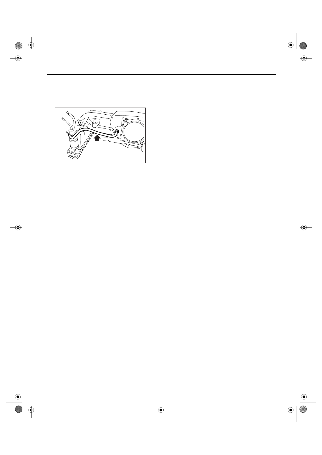
5) Connect the pressure regulator vacuum hose to
intake manifold.

6) Install the EGR valve. <Ref. to FU(H6DO)-25,
INSTALLATION, EGR Valve.>
7) Install the throttle body to intake manifold. <Ref.
to FU(H6DO)-11, INSTALLATION, Throttle Body.>
8) Install the engine harness to intake manifold.

E: INSPECTION

Make sure the fuel pipe and fuel hoses are not
damaged and the connections are tightened firmly.

FU-02123

FU(H6DO)-18

FUEL INJECTION (FUEL SYSTEMS)

Engine Coolant Temperature Sensor

4. Engine Coolant Temperature 

Sensor

A: REMOVAL

1) Remove the collector cover.
2) Disconnect the ground cable from battery.

3) Disconnect the connectors from engine coolant
temperature sensor.
4) Remove the engine coolant temperature sensor.

B: INSTALLATION

Install in the reverse order of removal.

Tightening torque:

18 N

m (1.8 kgf-m, 13 ft-lb)

IN-00203

FU-00572

FU-00572

FU(H6DO)-19

FUEL INJECTION (FUEL SYSTEMS)

Crankshaft Position Sensor

5. Crankshaft Position Sensor

A: REMOVAL

1) Remove the collector cover.
2) Disconnect the ground cable from battery.

3) Remove the air intake chamber. <Ref. to
IN(H6DO)-7, REMOVAL, Air Intake Chamber.>
4) Remove the service hole cover.

5) Remove the crankshaft position sensor.

6) Disconnect the connector from crankshaft posi-
tion sensor.

B: INSTALLATION

Install in the reverse order of removal.

Tightening torque:

6.4 N

m (0.65 kgf-m, 4.7 ft-lb)

IN-00203

FU-02127

FU-02128

FU-02128

FU(H6DO)-20

FUEL INJECTION (FUEL SYSTEMS)

Camshaft Position Sensor

6. Camshaft Position Sensor

A: REMOVAL

1) Remove the collector cover.
2) Disconnect the ground cable from battery.

3) Remove the generator harness from fuel pipe
protector LH.
4) Remove the fuel pipe protector LH.

5) Disconnect the connector from camshaft posi-
tion sensor LH.

6) Remove the camshaft position sensor LH.

7) Remove the camshaft position sensor RH in the
same procedure as LH.

B: INSTALLATION

Install in the reverse order of removal.

Tightening torque:

Camshaft position sensor

6.4 N

m (0.65 kgf-m, 4.7 ft-lb)

Fuel pipe protector

19 N

m (1.9 kgf-m, 14 ft-lb)

IN-00203

FU-02117

FU-02129

FU-02130


Content   ..  364  365  366  367   ..