Subaru Legacy (2005 year). Manual - part 321
 

  Index      Subaru     Subaru Legacy - service repair manual 2005 year


Search            


Content   ..  319  320  321  322   ..


Subaru Legacy (2005 year). Manual - part 321


EN(H4DOTC)(diag)-53

ENGINE (DIAGNOSTICS)

Diagnostics for Engine Starting Failure

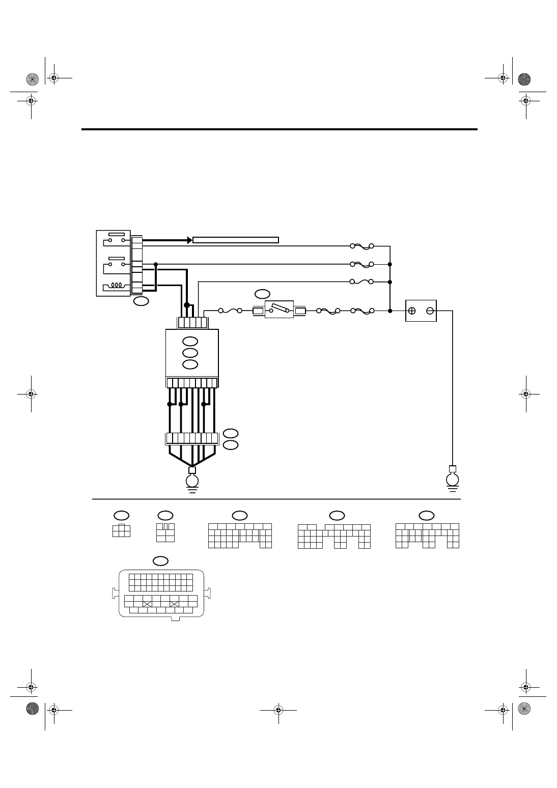
C: CHECK POWER SUPPLY AND GROUND LINE OF ENGINE CONTROL MOD-

ULE (ECM)

CAUTION:
After repair or replacement of faulty parts, perform Clear Memory Mode <Ref. to EN(H4DOTC)(diag)-
37, OPERATION, Clear Memory Mode.> 
and Inspection Mode <Ref. to EN(H4DOTC)(diag)-30, PROCE-
DURE, Inspection Mode.>.
WIRING DIAGRAM:

EN-03519

B72

BATTERY

MAIN RELAY

SBF-6

MAIN SBF

SBF-7

No.13

SBF-5

B72

TO FRONT OXYGEN(A/F) SENSOR

D16

A6

A7

B1

B4

D7

B12

D1

D2

D3

B5

B6

B19

D14

No.12

B47

E2

B21

2

1

4

6

5

3

ECM

E

E

3

6

B134

B135

B137

A:

B:

D:

54

35

36

12

34

3

4

1

2

5

6

B47

B21

B134

A:

B137

D:

B135

B:

IGNITION
SWITCH

5

6

7

8

2

1

9

4

3

10

24

22 23

25

11 12 13 14 15

26 27

28

16 17

18 19 20 21

33 34

29

32

30 31

5

6

7

8

2

1

9

4

3

10

24

22 23

25

11 12 13 14 15

26 27

28

16 17 18 19

20 21

29 30 31

32 33

34 35

5

6

7

8

2

1

9

4

3

10

22 23

11 12 13 14 15

24 25

26

16 17

18 19 20 21

27

28 29

30 31

37

1

3

4 5 6

2

1 2 3 4

12 13 14 15

5 6 7 8

16 17 18 19

9 10 11

20 21 22

23 24 25 26 27 28 29 30 31 32 33

35

34

37

36

39

38

41

40

43

42

44

45

47

46

49

48

51

50

53

52

54

EN(H4DOTC)(diag)-54

ENGINE (DIAGNOSTICS)

Diagnostics for Engine Starting Failure

Step

Check

Yes

No

1

CHECK MAIN RELAY.
1) Turn the ignition switch to OFF.
2) Remove the main relay.
3) Connect the battery to main relay terminals 
No. 1 and No. 2.
4) Measure the resistance between main relay 
terminals.

Terminals

No. 3 — No. 5:
No. 4 — No. 6:

Is the resistance less than 10 
Ω?

Go to step 2.

Replace the main 
relay.

2

CHECK GROUND CIRCUIT FOR ECM.
1) Disconnect the connector from ECM.
2) Measure the resistance of harness 
between ECM and chassis ground.

Connector & terminal

(B134) No. 6 — Chassis ground:
(B134) No. 7 — Chassis ground:
(B135) No. 1 — Chassis ground:
(B135) No. 4 — Chassis ground:
(B135) No. 12 — Chassis ground:
(B137) No. 1 — Chassis ground:
(B137) No. 2 — Chassis ground:
(B137) No. 3 — Chassis ground:
(B137) No. 7 — Chassis ground:

Is the resistance less than 5 
Ω?

Go to step 3.

Repair the open 
circuit of harness 
between ECM 
connector and 
engine grounding 
terminal.

3

CHECK INPUT VOLTAGE OF ECM.
Measure the voltage between ECM connector 
and chassis ground.

Connector & terminal

(B135) No. 19 (+) — Chassis ground (

):

Is the voltage more than 10 V? Go to step 4.

Repair the open or 
ground short cir-
cuit of power sup-
ply circuit.

4

CHECK INPUT VOLTAGE OF ECM.
1) Turn the ignition switch to ON.
2) Measure the voltage between ECM con-
nector and chassis ground.

Connector & terminal

(B137) No. 14 (+) — Chassis ground (

):

Is the voltage more than 10 V? Go to step 5.

Repair the open or 
ground short cir-
cuit of power sup-
ply circuit.

5

CHECK INPUT VOLTAGE OF MAIN RELAY.
Measure the voltage between main relay con-
nector and chassis ground.

Connector & terminal

(B47) No. 2 (+) — Chassis ground (

):

(B47) No. 5 (+) — Chassis ground (

):

(B47) No. 6 (+) — Chassis ground (

):

Is the voltage more than 10 V? Go to step 6.

Repair the open or 
ground short cir-
cuit of harness of 
power supply cir-
cuit.

6

CHECK INPUT VOLTAGE OF ECM.
1) Connect the main relay connector.
2) Turn the ignition switch to ON.
3) Measure the voltage between ECM con-
nector and chassis ground.

Connector & terminal

(B135) No. 5 (+) — Chassis ground (

):

(B135) No. 6 (+) — Chassis ground (

):

Is the voltage more than 10 V? Check ignition 

control system. 
<Ref. to 
EN(H4DOTC)(diag
)-55, IGNITION 
CONTROL SYS-
TEM, Diagnostics 
for Engine Start-
ing Failure.>

Repair the open or 
ground short cir-
cuit of harness 
between ECM 
connector and 
main relay connec-
tor.

EN(H4DOTC)(diag)-55

ENGINE (DIAGNOSTICS)

Diagnostics for Engine Starting Failure

D: IGNITION CONTROL SYSTEM

CAUTION:
After repair or replacement of faulty parts, perform Clear Memory Mode <Ref. to EN(H4DOTC)(diag)-
37, OPERATION, Clear Memory Mode.> 
and Inspection Mode <Ref. to EN(H4DOTC)(diag)-30, PROCE-
DURE, Inspection Mode.>.
WIRING DIAGRAM:

EN-03520

SBF-6

MAIN SBF

B72

B135

18

17

16

15

ECM

No.12

E

E

6

3

E2

B21

E31

E31

E32

E33

E34

No.1

E32

E33

E34

1
2
3

B21

3

1

2

3

1

2

13

49

14

15

16

3

1

2

3

1

2

IGNITION
SWITCH

IGNITION COIL

No.2

IGNITION COIL

No.3

IGNITION COIL

No.4

IGNITION COIL

B135

B72

5

6

7

8

2

1

9

4

3

10

24

22 23

25

11 12 13 14 15

26 27

28

16 17 18 19

20 21

29 30 31

32 33

34 35

1 2 3 4

12 13 14 15

5 6 7 8

16 17 18 19

9 10 11

20 21 22

23 24 25 26 27 28 29 30 31 32 33

35

34

37

36

39

38

41

40

43

42

44

45

47

46

49

48

51

50

53

52

54

1

3

4 5 6

2

EN(H4DOTC)(diag)-56

ENGINE (DIAGNOSTICS)

Diagnostics for Engine Starting Failure

Step

Check

Yes

No

1

CHECK CONDITION OF SPARK PLUG.
1) Remove the spark plug. <Ref. to 
IG(H4DOTC)-4, REMOVAL, Spark Plug.>
2) Check the spark plug condition. <Ref. to 
IG(H4DOTC)-5, INSPECTION, Spark Plug.>

Is the spark plug in normal 
condition?

Go to step 2.

Replace the spark 
plug.

2

CHECK SPARK OF IGNITION SYSTEM.
1) Connect the spark plug to ignition coil.
2) Release the fuel pressure. <Ref. to 
FU(H4DOTC)-39, RELEASING OF FUEL 
PRESSURE, PROCEDURE, Fuel.>
3) Contact the spark plug thread portion on 
engine.
4) While opening the throttle valve fully, crank 
the engine to check that spark occurs at each 
cylinder.

Does spark occur at each cyl-
inder?

Check the fuel 
pump system. 
<Ref. to 
EN(H4DOTC)(diag
)-58, FUEL PUMP 
CIRCUIT, Diag-
nostics for Engine 
Starting Failure.>

Go to step 3.

3

CHECK POWER SUPPLY CIRCUIT OF IGNI-
TION COIL.
1) Turn the ignition switch to OFF.
2) Disconnect the connector from ignition coil.
3) Turn the ignition switch to ON.
4) Measure the power supply voltage between 
ignition coil connector and engine ground.

Connector & terminal

(E31) No. 3 (+) — Engine ground (

):

(E32) No. 3 (+) — Engine ground (

):

(E33) No. 3 (+) — Engine ground (

):

(E34) No. 3 (+) — Engine ground (

):

Is the voltage more than 10 V? Go to step 4.

Repair the har-
ness and connec-
tor.

NOTE:
In this case, repair
the following:
• Open circuit of 
harness between 
ignition coil and 
ignition switch con-
nector
• Poor contact in 
coupling connector

4

CHECK HARNESS OF IGNITION COIL 
GROUND CIRCUIT.
1) Turn the ignition switch to OFF.
2) Measure the resistance between ignition 
coil connector and engine ground.

Connector & terminal

(E31) No. 2 — Engine ground:
(E32) No. 2 — Engine ground:
(E33) No. 2 — Engine ground:
(E34) No. 2 — Engine ground:

Is the resistance less than 5 
Ω?

Go to step 5.

Repair the har-
ness and connec-
tor.

NOTE:
In this case, repair
the following:
• Open circuit of 
harness between 
ignition coil con-
nector and engine 
ground terminal

5

CHECK HARNESS BETWEEN ECM AND IG-
NITION COIL CONNECTOR.
1) Turn the ignition switch to OFF.
2) Disconnect the connector from ECM.
3) Disconnect the connector from ignition coil.
4) Measure the resistance of harness 
between ECM and ignition coil connector.

Connector & terminal

(B135) No. 15 — (E34) No. 1:
(B135) No. 16 — (E33) No. 1:
(B135) No. 17 — (E32) No. 1:
(B135) No. 18 — (E31) No. 1:

Is the resistance less than 1 
Ω?

Go to step 6.

Repair the har-
ness and connec-
tor.

NOTE:
In this case, repair
the following:
• Open circuit of 
harness between 
ECM and ignition 
coil connector
• Poor contact in 
coupling connector

6

CHECK HARNESS BETWEEN ECM AND IG-
NITION COIL CONNECTOR.
Measure the resistance of harness between 
ECM and engine ground.

Connector & terminal

(B135) No. 15 — Engine ground:
(B135) No. 16 — Engine ground:
(B135) No. 17 — Engine ground:
(B135) No. 18 — Engine ground:

Is the resistance more than 1 
M

Ω?

Go to step 7.

Repair the ground 
short circuit of har-
ness between 
ECM and ignition 
coil connector.


Content   ..  319  320  321  322   ..