Subaru Legacy (2005 year). Manual - part 281


  Index      Subaru     Subaru Legacy - service repair manual 2005 year


Search            


Content   ..  279  280  281  282   ..


Subaru Legacy (2005 year). Manual - part 281


ME(H4DOTC)-67

MECHANICAL

Cylinder Head

4. INTAKE AND EXHAUST VALVE

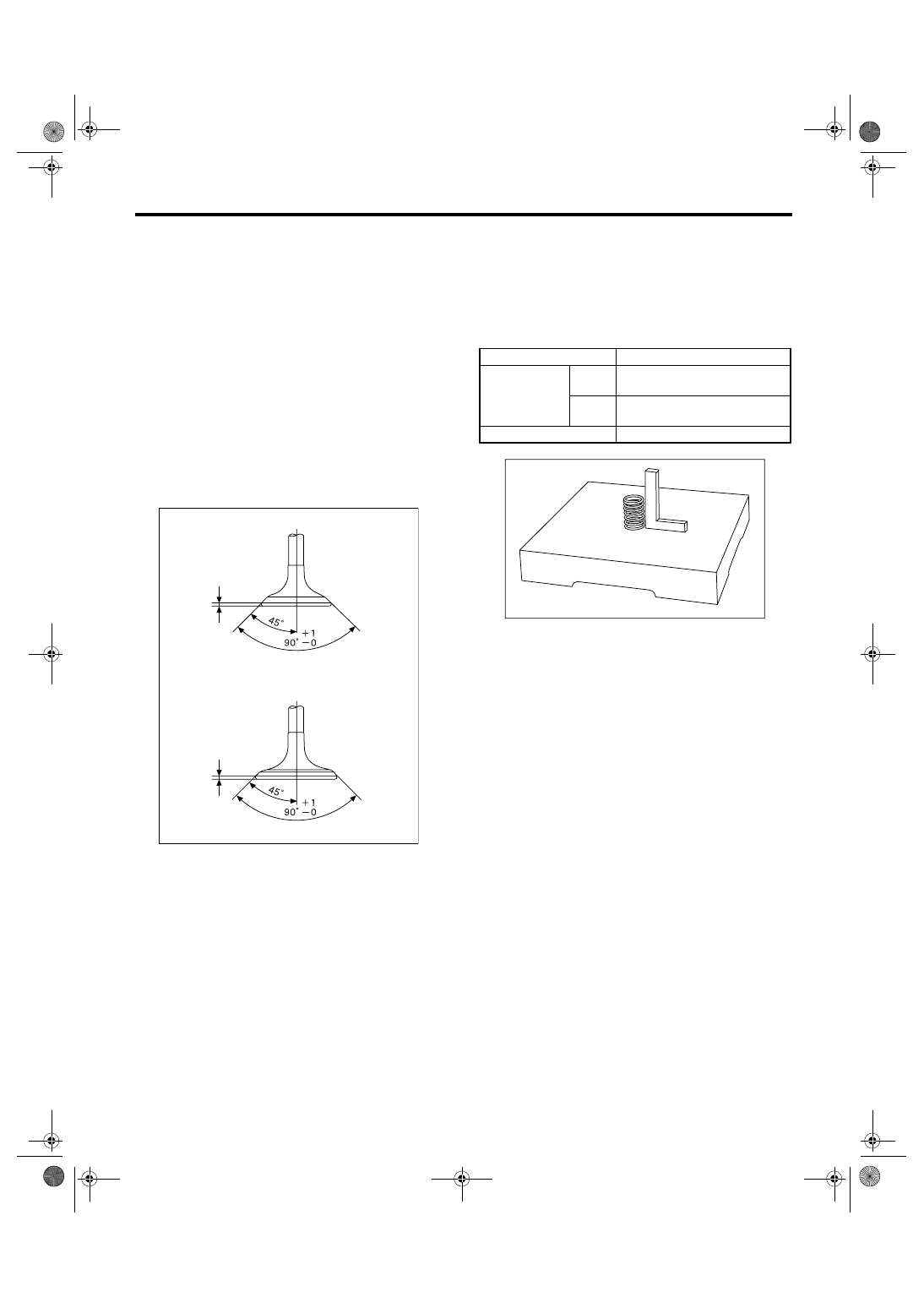
1) Inspect the flange and stem of valve, and re-
place if damaged, worn or deformed, or if “H” ex-
ceeds the standard or offset wear occurs.

Head edge thickness H:

Intake (A)
Standard

1.0 — 1.4 mm (0.039 — 0.055 in)

Exhaust (B)
Standard

1.3 — 1.7 mm (0.051 — 0.067 in)

Valve overall length:

Intake (A)

104.4 mm (4.110 in)

Exhaust (B)

104.65 mm (4.1201 in)

2) Put a small amount of grinding compound on the
seat surface and lap the valve and seat surface. In-
stall a new intake valve oil seal after lapping.

5. VALVE SPRING

1) Check the valve springs for damage, free length,
and tension. Replace the valve spring if it is not
within the standard presented in the table.
2) To measure the squareness of the valve spring,
stand the spring on a surface plate and measure its
deflection at the top of spring using a try square.

ME-00758

H

H

(B)

(A)

Free length

mm (in) 44.67 (1.759)

Tension/spring 
height

Set

206 — 236 (21.0 — 24.1, 46.3 — 
53.1)/36.0 (1.417)

N (kgf, lbf)/mm

(in)

Lift

485 — 537 (21.0 — 24.1, 109 — 
121)/26.6 (1.047)

Squareness

2.5

°, 2.0 mm (0.079 in)

ME-00132

ME(H4DOTC)-68

MECHANICAL

Cylinder Head

6. INTAKE AND EXHAUST VALVE OIL 
SEAL 

Replace the oil seal with a new one, if the lip is
damaged or spring is out of place, or when the sur-
faces of intake valve and valve seat are recondi-
tioned or intake valve guide is replaced.
1) Place the cylinder head on ST1.
2) Press-fit the oil seal to the specified dimension
indicated in the figure using ST2.
ST1

498267600

CYLINDER HEAD TABLE

ST2

498857100

VALVE OIL SEAL GUIDE

NOTE:
• Apply engine oil to oil seal before force-fitting.
• Differentiate between the intake valve oil seal
and exhaust valve oil seal by noting their difference
in color.

Color of rubber part:

Intake [Gray]
Exhaust [Green]

7. VALVE LIFTER

1) Check the valve lifter visually.
2) Measure the outer diameter of valve lifter.

Outer diameter:

34.959 — 34.975 mm (1.3763 — 1.3770 in)

3) Measure the inner diameter of valve lifter mating
part on cylinder head.

Inner diameter:

34.994 — 35.016 mm (1.3777 — 1.3786 in)

NOTE:
If difference between outer diameter of valve lifter
and inner diameter of valve lifter mating part ex-
ceeds the standard or offset wear occurs, replace
the cylinder head.

Standard:

0.019 — 0.057 mm (0.0007 — 0.0022 in)

ME-00133

ST2

ME-00134

ME-00135

ME(H4DOTC)-69

MECHANICAL

Cylinder Block

21.Cylinder Block

A: REMOVAL

NOTE:
Before conducting this procedure, drain engine oil
completely.
1) Remove the intake manifold.
<Ref. to FU(H4DOTC)-12, REMOVAL, Intake Man-
ifold.>
2) Remove the V-belts. <Ref. to ME(H4DOTC)-40,
REMOVAL, V-belt.>
3) Remove the crank pulley.
<Ref. to ME(H4DOTC)-43, REMOVAL, Crank Pul-
ley.>
4) Remove the timing belt cover.
<Ref. to ME(H4DOTC)-45, REMOVAL, Timing Belt
Cover.>
5) Remove the timing belt.
<Ref. to ME(H4DOTC)-46, REMOVAL, Timing
Belt.>
6) Remove the cam sprocket.
<Ref. to ME(H4DOTC)-54, REMOVAL, Cam
Sprocket.>
7) Remove the crank sprocket.
<Ref. to ME(H4DOTC)-55, REMOVAL, Crank
Sprocket.>
8) Remove the generator and A/C compressor with
their brackets.
9) Remove the cylinder head.
<Ref. to ME(H4DOTC)-62, REMOVAL, Cylinder
Head.>
10) Remove the clutch disc and cover. (MT model)
<Ref. to CL-16, REMOVAL, Clutch Disc and Cov-
er.>
11) Remove the flywheel. (MT model)
<Ref. to CL-16, REMOVAL, Clutch Disc and Cov-
er.>
ST

498497100

CRANKSHAFT STOPPER

12) Remove the drive plate. (AT model)
Use the ST to lock crankshaft.
ST

498497100

CRANKSHAFT STOPPER

13) Remove the oil separator cover.
14) Remove the water by-pass pipe for heater.
15) Remove the water pump.
16) Remove the oil filter.
17) Remove the oil cooler. (MT model)

18) Removal of oil pan:

(1) Place the #2 and #4 cylinder side upward.
(2) Remove the bolts which secure oil pan to
cylinder block.
(3) Insert a oil pan cutter blade between cylin-
der block-to-oil pan clearance and remove the
oil pan. Do not use a screwdriver or similar tools
in place of oil pan cutter.

ME-00778

ST

(A) O-ring

(B) Oil cooler

(C) Oil cooler connector

ME-00136

ST

ME-00723

T2

(C)

(B)

(A)

T1

ME(H4DOTC)-70

MECHANICAL

Cylinder Block

19) Remove the oil pump from cylinder block using
flat tip screwdriver.

CAUTION:
Be careful not to scratch the mating surface of 
cylinder block and oil pump.

20) Remove the oil strainer stay.
21) Remove the oil strainer.
22) Remove the baffle plate.
23) Remove the water pipe.

ME-00138

(1)

Service hole plug

(3)

Snap ring

(5)

Service hole cover

(2)

Gasket

(4)

Piston pin

(6)

O-ring

ME-00139

(3)

(4)

(2)

(1)

(3)

(4)

(5)

(6)

(2)

(3)

(2)

(1)

(3)

(4)

(4)

(1)


Content   ..  279  280  281  282   ..