Subaru Legacy (2005 year). Manual - part 278
ME(H4DOTC)-55
MECHANICAL
Crank Sprocket
18.Crank Sprocket
A: REMOVAL
1) Remove the V-belts. <Ref. to ME(H4DOTC)-40,
REMOVAL, V-belt.>
2) Remove the crank pulley.
<Ref. to ME(H4DOTC)-43, REMOVAL, Crank Pul-
ley.>
3) Remove the timing belt cover.
<Ref. to ME(H4DOTC)-45, REMOVAL, Timing Belt
Cover.>
4) Remove the timing belt.
<Ref. to ME(H4DOTC)-46, REMOVAL, Timing
Belt.>
5) Remove the cam sprocket.
<Ref. to ME(H4DOTC)-54, REMOVAL, Cam
Sprocket.>
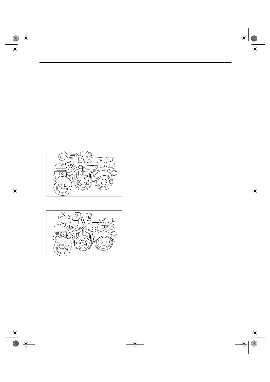
6) Remove the crank sprocket.
B: INSTALLATION
1) Install the crank sprocket.
2) Install the cam sprocket.
<Ref. to ME(H4DOTC)-54, INSTALLATION, Cam
Sprocket.>
3) Install the timing belt.
<Ref. to ME(H4DOTC)-48, INSTALLATION, Tim-
ing Belt.>
4) Install the timing belt cover.
<Ref. to ME(H4DOTC)-45, INSTALLATION, Tim-
ing Belt Cover.>
5) Install the crank pulley. <Ref. to ME(H4DOTC)-
43, INSTALLATION, Crank Pulley.>
6) Install the V-belts. <Ref. to ME(H4DOTC)-40,
INSTALLATION, V-belt.>
C: INSPECTION
1) Check the crank sprocket teeth for abnormal
wear and scratches.
2) Make sure there is no free play between crank
sprocket and key.
3) Check the crank sprocket protrusion used for
sensor for damage and contamination of foreign
matter.
ME-00103
ME-00103