Subaru Legacy (2005 year). Manual - part 254


  Index      Subaru     Subaru Legacy - service repair manual 2005 year


Search            


Content   ..  252  253  254  255   ..


Subaru Legacy (2005 year). Manual - part 254


FU(H4DOTC)-41

FUEL INJECTION (FUEL SYSTEMS)

Fuel Tank

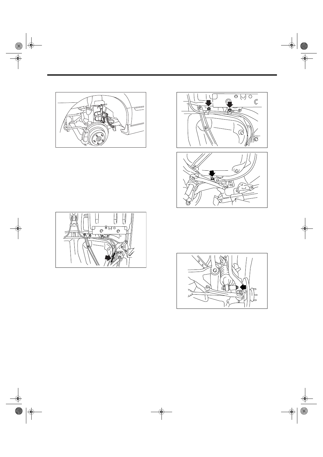
13) Remove the rear brake caliper and tie it to the
vehicle body side.

14) Remove the parking brake cable from parking
brake assembly. <Ref. to PB-6, REMOVAL, Park-
ing Brake Assembly (Rear Disc Brake).>
15) Remove the rear exhaust pipe.
<Ref. to EX(H4DOTC)-11, REMOVAL, Rear Ex-
haust Pipe.>
16) Remove the propeller shaft. <Ref. to DS-10,
REMOVAL, Propeller Shaft.>
17) Remove the heat shield cover.
18) Disconnect the connector from rear ABS wheel
speed sensor.

19) Remove the bolts which install parking brake
cable clamp.

20) Remove the rear suspension assembly.

CAUTION:
A helper is required to perform this work.

(1) Support the rear differential with transmis-
sion jack.
(2) Remove the bolt which installs rear shock
absorber to rear suspension arm.

FU-00462

FU-01129

FU-01130

FU-01131

FU-01132

FU(H4DOTC)-42

FUEL INJECTION (FUEL SYSTEMS)

Fuel Tank

(3) Remove the bolts which secure rear sus-
pension assembly to body.

(4) Remove the rear suspension assembly.

21) Disconnect the two-way valve hose (A) from
two-way valve, and then remove the two-way valve
from bracket.

22) Loosen the clamp and disconnect the fuel filler
hose (A) and vent hose (B) from fuel filler pipe.

23) Support the fuel tank with transmission jack, re-
move the bolts from fuel tank bands, and dismount
the fuel tank from vehicle.

WARNING:
A helper is required to perform this work.

B: INSTALLATION

1) Support the fuel tank with transmission jack, set
the fuel tank, and then temporarily tighten the bolts
of fuel tank band.

WARNING:
A helper is required to perform this work.

FU-01133

FU-01134

(A)

FU-01135

FU-01136

(A)

(B)

FU-01137

FU-01137

FU(H4DOTC)-43

FUEL INJECTION (FUEL SYSTEMS)

Fuel Tank

2) Correctly insert the fuel filler hose (A) and vent
hose (B) to the specified position, and then tighten
the clamp.

3) Install the two-way valve to bracket, and connect
the two-way valve hose (A) to two-way valve.

4) Tighten the bolts of fuel tank band.

Tightening torque:

33 N

m (3.4 kgf-m, 24.3 ft-lb)

5) Install the rear suspension assembly.

CAUTION:
A helper is required to perform this work.

(1) Support the rear differential with transmis-
sion jack.
(2) Support the rear suspension assembly, and
then tighten the bolts which secure the rear sus-
pension assembly to body.

Tightening torque:

T1: 125 N

m (12.7 kgf-m, 92.2 ft-lb)

T2: 65 N

m (6.2 kgf-m, 48 ft-lb)

T3: 175 N

m (17.8 kgf-m, 129 ft-lb)

(3) Tighten the bolts which install rear shock ab-
sorber to rear suspension arm. <Ref. to RS-11,
INSTALLATION, Rear Arm.>

Tightening torque:

62 N

m (6.3 kgf-m, 46 ft-lb)

(1) Hose

(2) Clip or clamp

(3) Pipe

FU-01136

(A)

(B)

( 1 )

( 2 )

( 3 )

FU-00104

L

L/2

(A)

FU-01135

FU-01150

T1

T1

T1

T1

FU-01138

T3

T3

T2

T2

FU-01132

FU(H4DOTC)-44

FUEL INJECTION (FUEL SYSTEMS)

Fuel Tank

6) Tighten the bolts which install parking brake ca-
ble clamp.

Tightening torque:

18 N

m (1.8 kgf-m, 13.0 ft-lb)

Tightening torque:

33 N

m (3.4 kgf-m, 24.3 ft-lb)

7) Connect the connector to rear ABS wheel speed
sensor.

8) Install the heat shield cover.

Tightening torque:

17.5 N

m (1.78 kgf-m, 12.9 ft-lb)

9) Install the propeller shaft. <Ref. to DS-11, IN-
STALLATION, Propeller Shaft.>
10) Install the rear exhaust pipe. <Ref. to
EX(H4DOTC)-11, INSTALLATION, Rear Exhaust
Pipe.>
11) Lower the vehicle.
12) Connect the parking brake cable to parking
brake assembly. <Ref. to PB-7, INSTALLATION,
Parking Brake Assembly (Rear Disc Brake).>
13) Install the rear brake caliper.

14) Tighten the bolt which secures rear brake hose
installation bracket.

Tightening torque:

33 N

m (3.4 kgf-m, 24.3 ft-lb)

15) Install the rear wheels.
16) Lower the vehicle.
17) Connect the connector (A) to fuel sub level sen-
sor.
18) Connect the quick connector to the fuel delivery
(B) and return hose (C). <Ref. to FU(H4DOTC)-56,
INSTALLATION, Fuel Delivery, Return and Evapo-
ration Lines.>

NOTE:
Be careful not to misconnect the delivery side and
return side.

19) Install the service hole cover of fuel sub level
sensor.

FU-01130

FU-01131

FU-01129

(A) Bolt

(B) Grommet

FU-01128

 FU-01127

(A)

(B)

(C)

FU-01126

(B)

(A)

(A)


Content   ..  252  253  254  255   ..