Subaru Legacy (2005 year). Manual - part 193


  Index      Subaru     Subaru Legacy - service repair manual 2005 year


Search            


Content   ..  191  192  193  194   ..


Subaru Legacy (2005 year). Manual - part 193


EN(H4SO 2.5)(diag)-57

ENGINE (DIAGNOSTICS)

Diagnostics for Engine Starting Failure

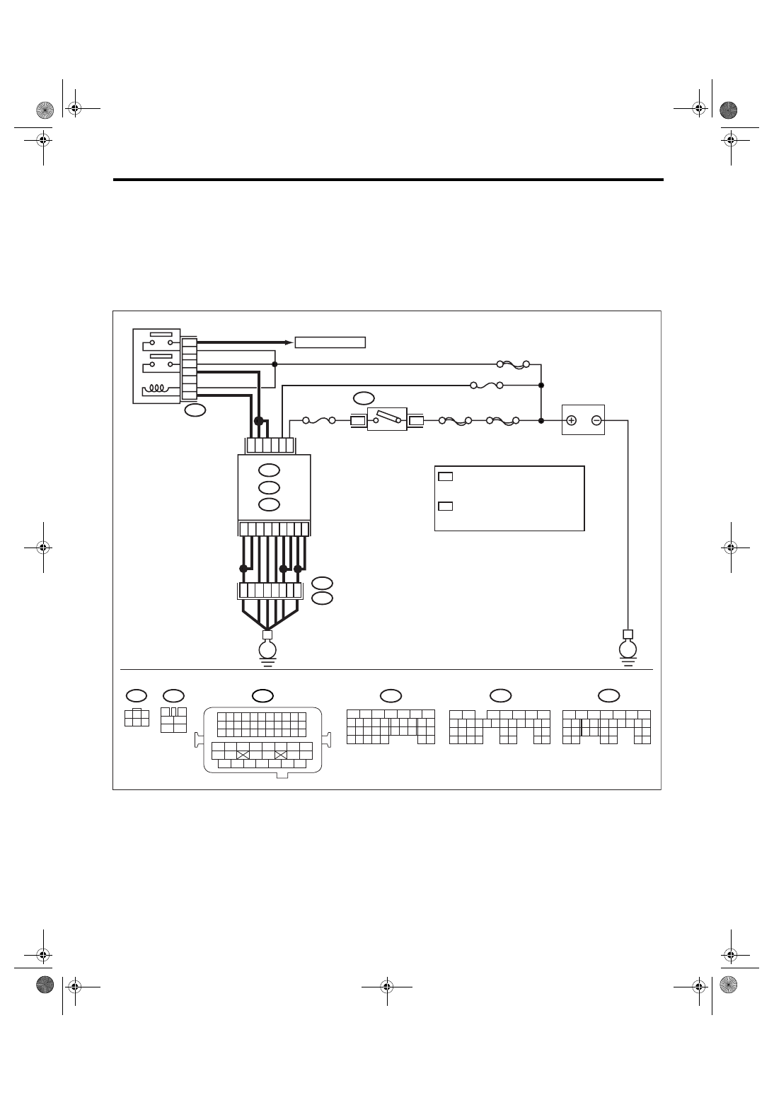
C: CHECK POWER SUPPLY AND GROUND LINE OF ENGINE CONTROL MOD-

ULE (ECM)

CAUTION:
After repair or replacement of faulty parts, conduct Clear Memory Mode <Ref. to EN(H4SO 2.5)(diag)-
40, OPERATION, Clear Memory Mode.> 
and Inspection Mode <Ref. to EN(H4SO 2.5)(diag)-33, PRO-
CEDURE, Inspection Mode.>.
WIRING DIAGRAM:
• EC, EK, EH, ER and K4 model

• KA and KS model

NOTE:
Fuel injection system for KA and KS model is the same as 2.0 L model. Refer to EN(H4SO 2.0) section.

EN-03511

SBF-6

MAIN SBF

SBF-7

B72

B6

B5

A6

D2

A7

B12

D3

D7

D1

B19

No.12

B47

E2

B21

6

5

E

E

3

6

B134

B135

A:

D: B137

B:

B4

52

37

36

34

47

3

4

1

2

5

6

B47

No.13

B1

35

B134

5

6

7

8

2

1

9

4

3

10

24

22 23

25

11 12 13 14 15

26 27

28

16 17

18 19 20 21

33 34

29

32

30 31

B135

5

6

7

8

2

1

9

4

3

10

24

22 23

25

11 12 13 14 15

26 27

28

16 17 18 19

20 21

29 30 31

32 33

34 35

B137

5

6

7

8

2

1

9

4

3

10

22 23

11 12 13 14 15

24 25

26

16 17

18 19 20 21

27

28 29

30 31

B21

1 2 3 4

12 13 14 15

5 6 7 8

16 17 18 19

9 10 11

20 21 22

23 24 25 26 27 28 29 30 31 32 33

35

34

37

36

39

38

41

40

43

42

44

45

47

46

49

48

51

50

53

52

54

B72

1

3

4 5 6

2

A:

B:

D:

1
2

1

*

2

*

4

3

ECM

1

*

2

*

MAIN RELAY

TO IGNITION COIL

IGNITION
SWITCH

BATTERY

LHD WITH IMMOBILIZER: D16
LHD WITHOUT IMMOBILIZER: D17
RHD : D16 

LHD WITH IMMOBILIZER: D14
LHD WITHOUT IMMOBILIZER: D15
RHD : D14

EN(H4SO 2.5)(diag)-58

ENGINE (DIAGNOSTICS)

Diagnostics for Engine Starting Failure

Step

Check

Yes

No

1

CHECK OPTION CODE.

Is the option code EC, EK, EH, 
ER or K4?

Go to step 2.

Refer to EN(H4SO 
2.0) section. <Ref. 
to EN(H4SO 
2.0)(diag)-64, List 
of Diagnostic Trou-
ble Code (DTC).>

NOTE:
Fuel injection sys-
tem for KA and KS
model is the same
as 2.0 L model.

2

CHECK MAIN RELAY.
1) Turn the ignition switch to OFF.
2) Remove the main relay.
3) Connect the battery to main relay terminals 
No. 1 and No. 2.
4) Measure the resistance between main relay 
terminals.

Terminals

No. 3 — No. 5:
No. 4 — No. 6:

Is the resistance less than 10 
Ω?

Go to step 3.

Replace the main 
relay.

3

CHECK GROUND CIRCUIT FOR ECM.
1) Disconnect the connector from ECM.
2) Measure the resistance of harness 
between ECM and chassis ground.

Connector & terminal

(B134) No. 6 — Chassis ground:
(B134) No. 7 — Chassis ground:
(B135) No. 1 — Chassis ground:
(B135) No. 4 — Chassis ground:
(B135) No. 12 — Chassis ground:
(B137) No. 1 — Chassis ground:
(B137) No. 2 — Chassis ground:
(B137) No. 3 — Chassis ground:
(B137) No. 7 — Chassis ground:

Is the resistance less than 5 
Ω?

Go to step 4.

Repair the open 
circuit of harness 
between ECM 
connector and 
engine grounding 
terminal.

4

CHECK INPUT VOLTAGE OF ECM.
Measure the voltage between ECM connector 
and chassis ground.

Connector & terminal

(B135) No. 19 (+) — Chassis ground (

):

Is the voltage more than 10 V? Go to step 5.

Repair the open or 
ground short cir-
cuit of power sup-
ply circuit.

5

CHECK INPUT VOLTAGE OF ECM.
1) Turn the ignition switch to ON.
2) Measure the voltage between ECM con-
nector and chassis ground.

Connector & terminal

RHD model

(B137) No. 14 (+) — Chassis ground (

):

LHD model with immobilizer

(B137) No. 14 (+) — Chassis ground (

):

LHD model without immobilizer

(B137) No. 15 (+) — Chassis ground (

):

Is the voltage more than 10 V? Go to step 6.

Repair the open or 
ground short cir-
cuit of power sup-
ply circuit.

6

CHECK INPUT VOLTAGE OF MAIN RELAY.
Measure the voltage between main relay con-
nector and chassis ground.

Connector & terminal

(B47) No. 1 (+) — Chassis ground (

):

Is the voltage more than 10 V? Go to step 7.

Repair the open 
circuit of harness 
between ECM 
connector and 
main relay connec-
tor.

EN(H4SO 2.5)(diag)-59

ENGINE (DIAGNOSTICS)

Diagnostics for Engine Starting Failure

7

CHECK INPUT VOLTAGE OF ECM.
1) Connect the connectors to ECM and main 
relay.
2) Turn the ignition switch to ON.
3) Measure the voltage between ECM con-
nector and chassis ground.

Connector & terminal

RHD model

(B137) No. 16 (+) — Chassis ground (

):

LHD model with immobilizer

(B137) No. 16 (+) — Chassis ground (

):

LHD model without immobilizer

(B137) No. 17 (+) — Chassis ground (

):

Is the voltage more than 10 V? Go to step 8.

Repair the open or 
ground short cir-
cuit of harness 
between ECM 
connector and 
main relay connec-
tor.

8

CHECK INPUT VOLTAGE OF MAIN RELAY.
Measure the voltage between main relay con-
nector and chassis ground.

Connector & terminal

(B47) No. 5 (+) — Chassis ground (

):

(B47) No. 6 (+) — Chassis ground (

):

Is the voltage more than 10 V? Go to step 9.

Repair the open or 
ground short cir-
cuit of harness of 
power supply cir-
cuit.

9

CHECK INPUT VOLTAGE OF ECM.
1) Turn the ignition switch to ON.
2) Measure the voltage between ECM con-
nector and chassis ground.

Connector & terminal

(B135) No. 5 (+) — Chassis ground (

):

(B135) No. 6 (+) — Chassis ground (

):

Is the voltage more than 10 V? Check ignition 

control system. 
<Ref. to EN(H4SO 
2.5)(diag)-60, 
IGNITION CON-
TROL SYSTEM, 
Diagnostics for 
Engine Starting 
Failure.>

Repair the open or 
ground short cir-
cuit of harness 
between ECM 
connector and 
main relay connec-
tor.

Step

Check

Yes

No

EN(H4SO 2.5)(diag)-60

ENGINE (DIAGNOSTICS)

Diagnostics for Engine Starting Failure

D: IGNITION CONTROL SYSTEM

CAUTION:
After repair or replacement of faulty parts, conduct Clear Memory Mode <Ref. to EN(H4SO 2.5)(diag)-
40, Clear Memory Mode.> and I
nspection Mode <Ref. to EN(H4SO 2.5)(diag)-33, Inspection Mode.>.
WIRING DIAGRAM:
• EC, EK, EH, ER and K4 model

• KA and KS model

NOTE:
Fuel injection system for KA and KS model is the same as 2.0 L model. Refer to EN(H4SO 2.0) section.

BATTERY

5

MAIN RELAY

17

B21

E2

E12

SBF-7

15A

13

49

15

1

2

3

4

B135

ECM

18

3

4

1

2

IGNITION COIL

&

IGNITOR ASSY

B47

E

E

1

2

RELAY HOLDER

B225

B135

5

6

7

8

2

1

9

4

3

10

24

22 23

25

11 12 13 14 15

26 27

28

16 17 18 19

20 21

29 30 31

32 33

34 35

B21

1 2 3 4

12 13 14 15

5 6 7 8

16 17 18 19

9 10 11

20 21 22

23 24 25 26 27 28 29 30 31 32 33

35

34

37

36

39

38

41

40

43

42

44

45

47

46

49

48

51

50

53

52

54

3

4

1

2

5

6

B47

1 2 3 4

E12

9

10

1

2

3

4

5

6

7

8

11 12

14

15 16

13

18

19 20

17

22

23 24

21

38

39 40

37

34

35 36

33

30

31 32

29

26

27 28

25

B225

EN-03454

3


Content   ..  191  192  193  194   ..