Subaru Legacy (2005 year). Manual - part 180
EN(H4SO 2.5)(diag)-5
ENGINE (DIAGNOSTICS)
General Description
3. General Description
A: CAUTION
1) Airbag system wiring harness is routed near the
ECM, main relay and fuel pump relay.
CAUTION:
• All airbag system wiring harnesses and con-
nectors are yellow. Do not use the electrical
test equipment on these circuits.
• Be careful not to damage the airbag system
wiring harness when servicing the ECM, TCM,
main relay and fuel pump relay.
2) Never connect the battery in reverse polarity.
• The ECM will be destroyed instantly.
• The fuel injector and other parts will be dam-
aged.
3) Do not disconnect the battery terminals while the
engine is running.
A large counter electromotive force will be generat-
ed in the generator, and this voltage may damage
electronic parts such as ECM.
4) Before disconnecting the connectors of each
sensor and ECM, be sure to turn the ignition switch
to OFF. Perform the clear memory mode after con-
necting the connectors.
5) Poor contact has been identified as a primary
cause of this problem. Measure the voltage or re-
sistance of each sensor or all electrical control
modules using a tapered pin with a diameter of less
than 0.64 mm (0.025 in). Do not insert the pin more
than 5 mm (0.20 in) into the part.
6) Before removing the ECM from the located posi-
tion, disconnect two cables on battery.
Otherwise, the ECM may be damaged.
CAUTION:
When replacing the ECM, be careful not to use
the ECM with wrong specifications to avoid any
damage on the fuel injection system.
NOTE:
Immobilizer system must be registered when in-
stalling the ECM of the model with immobilizer. For
doing so, all ignition keys and ID cards should be
prepared. Refer to “IMMOBILIZER TEACHING
OPERATION MANUAL”
7) Connectors of each sensor in the engine com-
partment and the harness connectors on the en-
gine / body side are all designed to be waterproof.
However, it is still necessary to take care not to al-
low water to get into the connectors when washing
the vehicle, or when servicing the vehicle on a rainy
day.
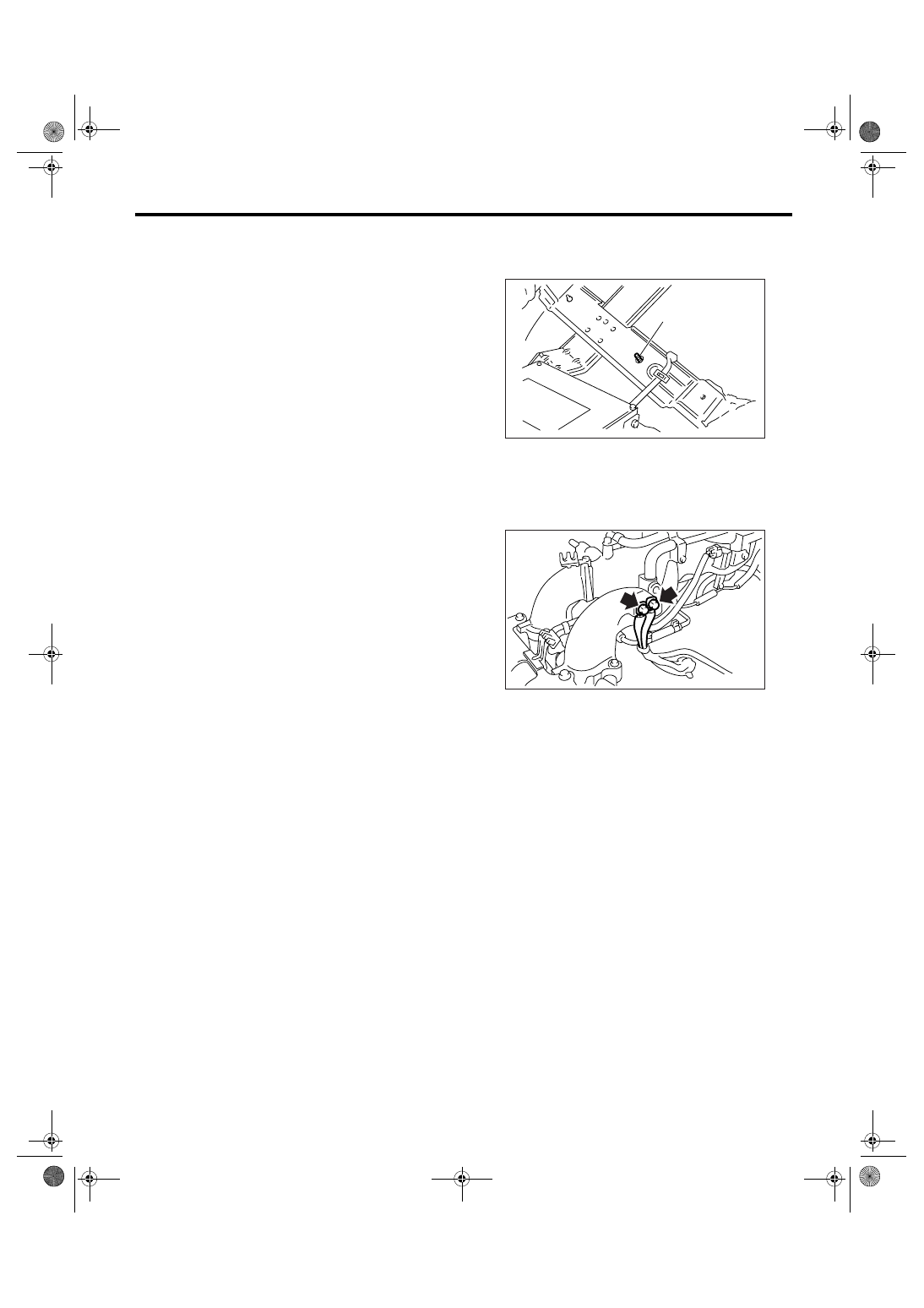
8) Use ECM mounting stud bolts the grounding
point to chassis when measuring voltage and resis-
tance inside the passenger compartment.
9) Use engine grounding terminal or engine as the
grounding point to chassis when measuring voltage
and resistance in the engine compartment.
10) Every MFI-related part is a precision part. Do
not drop them.
11) Observe the following cautions when installing
a radio in MFI equipped models.
CAUTION:
• The antenna must be kept as far apart as pos-
sible from the control module.
• The antenna feeder must be placed as far
apart as possible from the ECM and MFI har-
ness.
• Carefully adjust the antenna for correct
matching.
• When mounting a large power type radio, pay
special attention to the three items mentioned
above.
• Incorrect installation of the radio may affect
the operation of ECM.
12) Before disconnecting the fuel hose, disconnect
the fuel pump connector and crank the engine for
more than five seconds to release pressure in the
fuel system. If engine starts during this operation,
run until it stops.
(A) Stud bolt
EN-00001
(A)
FU-01090