Subaru Legacy (2005 year). Manual - part 167


  Index      Subaru     Subaru Legacy - service repair manual 2005 year


Search            


Content   ..  165  166  167  168   ..


Subaru Legacy (2005 year). Manual - part 167


FU(H4SO 2.5)-31

FUEL INJECTION (FUEL SYSTEMS)

EGR Valve

15.EGR Valve

A: REMOVAL

NOTE:
EGR valve is installed to EC, EK, K4 EH and ER
model.
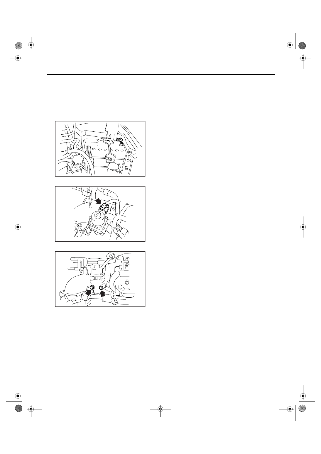
1) Disconnect the ground cable from battery.

2) Disconnect the connector from EGR valve.

3) Remove the EGR valve from intake manifold.

B: INSTALLATION

Install in the reverse order of removal.

NOTE:
Use a new gasket.

Tightening torque:

19 N

m (1.9 kgf-m, 14 ft-lb)

IN-00203

FU-01152

FU-01153

FU(H4SO 2.5)-32

FUEL INJECTION (FUEL SYSTEMS)

Fuel Injector

16.Fuel Injector

A: REMOVAL

1. RH SIDE

1) Release the fuel pressure. <Ref. to FU(H4SO
2.5)-41, RELEASING OF FUEL PRESSURE,
PROCEDURE, Fuel.>
2) Open the fuel filler flap lid, and remove the fuel
filler cap.
3) Disconnect the ground cable from battery.

4) Remove the air cleaner case. <Ref. to IN(H4SO
2.0)-5, REMOVAL, Air Cleaner Case.>
5) Remove the spark plug cords from spark plugs
(#1 and #3 cylinders).
6) Remove the fuel pipe protector RH.

7) Disconnect the connectors (A) from fuel injector.
8) Remove the harness band (B) which holds the
engine harness to injector pipe.

9) Remove the bolts which hold fuel injector pipe to
intake manifold.

10) Remove the fuel injector while lifting up the fuel
injector pipe.

2. LH SIDE

1) Release the fuel pressure. <Ref. to FU(H4SO
2.5)-41, RELEASING OF FUEL PRESSURE,
PROCEDURE, Fuel.>
2) Open the fuel filler flap lid, and remove the fuel
filler cap.
3) Remove the battery.
4) Remove the spark plug cords from spark plugs
(#2 and #4 cylinders).
5) Remove the fuel pipe protector LH.

6) Disconnect the connectors (A) from fuel injector.

IN-00203

FU-01094

FU-01336

(A)

(B)

FU-01098

FU-01110

FU-01093

FU(H4SO 2.5)-33

FUEL INJECTION (FUEL SYSTEMS)

Fuel Injector

7) Remove the harness band (B) which holds the
engine harness to injector pipe.

8) Remove the bolts which hold fuel injector pipe to
intake manifold.

9) Remove the fuel injector while lifting up the fuel
injector pipe.

B: INSTALLATION

1. RH SIDE

Install in the reverse order of removal.

NOTE:
• Use a new O-ring.
• O-ring (B) is used for EC, EK, K4, EH and ER
model.

Tightening torque:

19 N

m (1.9 kgf-m, 14 ft-lb)

Tightening torque:

19 N

m (1.9 kgf-m, 14 ft-lb)

FU-01338

(A)

(B)

(A)

FU-01099

FU-01100

FU-01110

(A) O-ring

(B) O-ring

(C) Fuel injector

(D) O-ring

FU-02157

(A)

(B)

(D)

(C)

FU-01098

FU-01094

FU(H4SO 2.5)-34

FUEL INJECTION (FUEL SYSTEMS)

Fuel Injector

2. LH SIDE

Install in the reverse order of removal.

NOTE:
• Use a new O-ring.
• O-ring (B) is used for EC, EK, K4, EH and ER
model.

Tightening torque:

6.4 N

m (0.65 kgf-m, 4.7 ft-lb)

Tightening torque:

19 N

m (1.9 kgf-m, 14 ft-lb)

Tightening torque:

19 N

m (1.9 kgf-m, 14 ft-lb)

(A) O-ring

(B) O-ring

(C) Fuel injector

(D) O-ring

FU-02157

(A)

(B)

(D)

(C)

FU-01100

FU-01099

FU-01093


Content   ..  165  166  167  168   ..