Subaru Legacy (2005 year). Manual - part 133
 

  Index      Subaru     Subaru Legacy - service repair manual 2005 year


Search            


Content   ..  131  132  133  134   ..


Subaru Legacy (2005 year). Manual - part 133


EN(H4SO 2.0)(diag)-121

ENGINE (DIAGNOSTICS)

Diagnostic Procedure with Diagnostic Trouble Code (DTC)

V: DTC P0139 O2 SENSOR CIRCUIT SLOW RESPONSE (BANK 1 SENSOR 2)

DTC DETECTING CONDITION:
Detects when malfunction occurs in 2 continuous driving cycles.

CAUTION:
After repair or replacement of faulty parts, perform Clear Memory Mode <Ref. to EN(H4SO 2.0)(diag)-
38, OPERATION, Clear Memory Mode.> 
and Inspection Mode <Ref. to EN(H4SO 2.0)(diag)-32, PRO-
CEDURE, Inspection Mode.>.
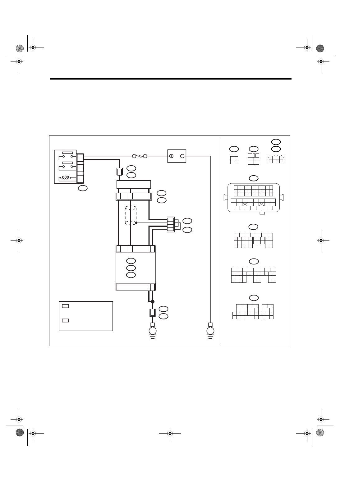
WIRING DIAGRAM:

EN-03476

B47

T5

3

4

5

6

1

2

1 2
3 4

BATTERY

B47

MAIN RELAY

1

2

4

6

3

5

A1

C19

C18

C30

B5

B6

REAR 
OXYGEN SENSOR

ECM

1

4

3

2

52

B21

T5

E2

1

B135

B:

SBF-5

C: B136

E

E

A: B134

B134

5

6

7

8

2

1

9

4

3

10

24

22 23

25

11 12 13 14 15

26 27

28

16 17

18 19 20 21

33 34

29

32

30 31

B136

5

6

7 8

2

1

9

4

3

10

24

22 23

25

11 12 13 14 15

26 27

28

16

17 18 19 20 21

33 34

29

32

30

31

35

B135

5

6

7

8

2

1

9

4

3

10

24

22 23

25

11 12 13 14 15

26 27

28

16 17 18 19

20 21

29 30 31

32 33

34 35

A:

B:

C:

B21

1 2 3 4

12 13 14 15

5 6 7 8

16 17 18 19

9 10 11

20 21 22

23 24 25 26 27 28 29 30 31 32 33

35

34

37

36

39

38

41

40

43

42

44

45

47

46

49

48

51

50

53

52

54

1 2 3 4
5 6 7 8

B138

B83

1

T5

B19

2

2

B19

B83

B138

:LHD

:RHD

*

*

*

*

1

*

: TERMINAL No. RANDOM
  ARRANGEMENT AMONG
  1,2,5, AND 6

2

*

: TERMINAL No. RANDOM
  ARRANGEMENT AMONG
  3,4,7, AND 8

EN(H4SO 2.0)(diag)-122

ENGINE (DIAGNOSTICS)

Diagnostic Procedure with Diagnostic Trouble Code (DTC)

Step

Check

Yes

No

1

CHECK FOR ANY OTHER DTC ON DIS-
PLAY.

Is any other DTC displayed?

Check DTC using 
“List of Diagnostic 
Trouble Code 
(DTC)”. <Ref. to 
EN(H4SO 
2.0)(diag)-64, List 
of Diagnostic Trou-
ble Code (DTC).>

NOTE:
In this case, it is
not necessary to
inspect DTC
P0139.

Go to step 2.

2

CHECK HARNESS BETWEEN ECM AND 
REAR OXYGEN SENSOR CONNECTOR.
1) Turn the ignition switch to OFF.
2) Disconnect the connectors from ECM and 
rear oxygen sensor.
3) Measure the resistance of harness 
between ECM and rear oxygen sensor con-
nector.

Connector & terminal

(B136) No. 19 — (B19) No. 4:

Is the resistance less than 1 
Ω?

Go to step 3.

Repair open circuit 
in harness 
between ECM and 
rear oxygen sen-
sor connector.

3

CHECK HARNESS BETWEEN REAR OXY-
GEN SENSOR AND ECM CONNECTOR.
Measure the resistance between rear oxygen 
sensor harness connector and chassis ground.

Connector & terminal

(B19) No. 4 — Chassis ground:

Is the resistance more than 1 
M

Ω?

Go to step 4.

Repair short circuit 
to ground in har-
ness.

4

CHECK REAR OXYGEN SENSOR DATA.
Measure the resistance between connector 
terminals of rear oxygen sensor.

terminals

No. 3 — No. 4:

Is the resistance less than 1 
Ω?

Replace the rear 
oxygen sensor. 
<Ref. to FU(H4SO 
2.0)-33, Rear Oxy-
gen Sensor.>

A temporary poor 
compact occurs. 
Check poor con-
tact in connector.

S008.fm  122 ページ  2007年12月3日 月曜日 午後1時41分

EN(H4SO 2.0)(diag)-123

ENGINE (DIAGNOSTICS)

Diagnostic Procedure with Diagnostic Trouble Code (DTC)

W: DTC P0171 SYSTEM TOO LEAN (BANK 1)

Refer to DTC P0172 for diagnostic procedure. <Ref. to EN(H4SO 2.0)(diag)-123, DTC P0172 SYSTEM TOO
RICH (BANK 1), Diagnostic Procedure with Diagnostic Trouble Code (DTC).>

X: DTC P0172 SYSTEM TOO RICH (BANK 1)

DTC DETECTING CONDITION:
Detects when malfunction occurs in 2 continuous driving cycles.
TROUBLE SYMPTOM:
• Erroneous idling
• Engine stalls.
• Poor driving performance

CAUTION:
After repair or replacement of faulty parts, perform Clear Memory Mode <Ref. to EN(H4SO 2.0)(diag)-
38, OPERATION, Clear Memory Mode.> 
and Inspection Mode <Ref. to EN(H4SO 2.0)(diag)-32, PRO-
CEDURE, Inspection Mode.>.

Step

Check

Yes

No

1

CHECK EXHAUST SYSTEM.

Are there holes or loose bolts 
on exhaust system?

Repair the exhaust 
system.

Go to step 2.

2

CHECK AIR INTAKE SYSTEM.

Are there holes, loose bolts or 
disconnection of hose on air 
intake system?

Repair the air 
intake system.

Go to step 3.

3

CHECK EGR VALVE.

Is the EGR valve stuck?

Replace the EGR 
valve.

Go to step 4.

4

CHECK PURGE CONTROL SOLENOID 
VALVE.

Is the purge control solenoid 
valve stuck?

Replace the purge 
control solenoid 
valve.

Go to step 5.

5

CHECK PCV VALVE.

Is the PCV valve stuck?

Replace the PCV 
valve.

Go to step 6.

6

CHECK FUEL PRESSURE.

Warning:

• Place “NO FIRE” signs near the working 
area.
• Be careful not to spill fuel.

1) Release the fuel pressure.

(1) Disconnect the connector from fuel 
pump relay.
(2) Start the engine and run until it stalls.
(3) After the engine stalls, crank it for five 
more seconds.
(4) Turn the ignition switch to OFF.

2) Connect the connector to fuel pump relay.
3) Disconnect the fuel delivery hose, and con-
nect the fuel pressure gauge.
4) Install the fuel filler cap.
5) Start the engine and idle while gear posi-
tion is neutral.
6) Measure the fuel pressure while discon-
necting pressure regulator vacuum hose from 
intake manifold.

Warning:

Release fuel pressure before removing the
fuel pressure gauge.

NOTE:

If fuel pressure does not increase, squeeze fuel
return hose 2 to 3 times, then measure fuel
pressure again.

Is fuel pressure 284 — 314 

kPa (2.9 — 3.2 kgf/cm

2

, 41 — 

46 psi)?

Go to step 7.

Repair the follow-
ing items.
Fuel pressure is 
too high:

• Clogged fuel 
return line or 
bent hose

Fuel pressure is 
too low:

• Improper fuel 
pump discharge
• Clogged fuel 
supply line

EN(H4SO 2.0)(diag)-124

ENGINE (DIAGNOSTICS)

Diagnostic Procedure with Diagnostic Trouble Code (DTC)

7

CHECK FUEL PRESSURE.
After connecting the pressure regulator vac-
uum hose, measure fuel pressure.

Warning:

Release fuel pressure before removing the
fuel pressure gauge.

NOTE:

• If fuel pressure does not increase, squeeze 
fuel return hose 2 to 3 times, then measure 
fuel pressure again.
• If the measured value at this step is out of 
specification, check or replace pressure regu-
lator and pressure regulator vacuum hose.

Is fuel pressure 206 — 235 

kPa (2.1 — 2.4 kgf/cm

2

, 30 — 

34 psi)?

Go to step 8.

Repair the follow-
ing items.
Fuel pressure is 
too high:

• Faulty pres-
sure regulator
• Clogged fuel 
return line or 
bent hose

Fuel pressure is 
too low:

• Faulty pres-
sure regulator
• Improper fuel 
pump discharge
• Clogged fuel 
supply line

8

CHECK ENGINE COOLANT TEMPERATURE 
SENSOR.
1) Start the engine and warm-up completely.
2) Read the data of engine coolant tempera-
ture sensor signal using Subaru Select Monitor 
or general scan tool.

NOTE:

• Subaru Select Monitor
For detailed operation procedure, refer to 
“READ CURRENT DATA FOR ENGINE”. <Ref. 
to EN(H4SO 2.0)(diag)-25, Subaru Select 
Monitor.>
• General scan tool
For detailed operation procedure, refer to the 
general scan tool operation manual.

Is the engine coolant tempera-
ture 70

°C (158°F — 100°C 

(212

°F)?

Go to step 9.

Replace the 
engine coolant 
temperature sen-
sor. <Ref. to 
FU(H4SO 2.0)-20, 
Engine Coolant 
Temperature Sen-
sor.>

9

CHECK MANIFOLD ABSOLUTE PRESSURE 
SENSOR SIGNAL.
1) Start and warm-up the engine until engine 
coolant temperature is above 60

°C (140°F).

2) Place the select lever in “N” or “P” position.
3) Turn the A/C switch to OFF.
4) Turn all the accessory switches to OFF.
5) Read the data of manifold absolute pres-
sure sensor signal using Subaru Select Moni-
tor or general scan tool.

NOTE:

• Subaru Select Monitor
For detailed operation procedure, refer to 
“READ CURRENT DATA FOR ENGINE”. <Ref. 
to EN(H4SO 2.0)(diag)-25, Subaru Select 
Monitor.>
• General scan tool
For detailed operation procedure, refer to the 
general scan tool operation manual.

Is the measurement value 24.0 
— 41.3 kPa (180 — 310 
mmHg, 7.09 — 12.20 inHg) 
when idling, and 73.3 — 106.6 
kPa (550 — 800 mmHg, 21.65 
— 31.50 inHg) when ignition 
turned ON?

Replace the ECM. 
<Ref. to FU(H4SO 
2.0)-34, Engine 
Control Module 
(ECM).>

Replace the mani-
fold absolute pres-
sure sensor. <Ref. 
to FU(H4SO 2.0)-
26, Manifold Abso-
lute Pressure Sen-
sor.>

Step

Check

Yes

No


Content   ..  131  132  133  134   ..