Subaru Legacy (2005 year). Manual - part 1048


  Index      Subaru     Subaru Legacy - service repair manual 2005 year


Search            


Content   ..  1046  1047  1048  1049   ..


Subaru Legacy (2005 year). Manual - part 1048
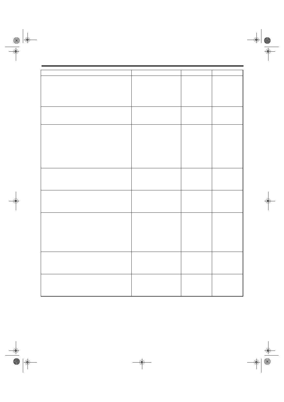


LAN(diag)-71

LAN SYSTEM (DIAGNOSTICS)

Diagnostic Procedure with Diagnostic Trouble Code (DTC)

4

CHECK CURRENT DATA.
Connect the Subaru Select Monitor and dis-
play current data of the body integrated unit 
(auto A/C fail). 

Is OK displayed?

Go to step 5.

Perform auto A/C 
self-diagnosis. 
<Ref. to AC(diag)-
10, OPERATION, 
Diagnostic Chart 
for Self-Diagno-
sis.>

5

CHECK AUTO A/C ECM.
1) Turn the ignition switch to OFF.
2) Disconnect the auto A/C ECM connector.
3) Turn the ignition switch to ON.

Does the communications 
error display disappear?

Go to step 6.

Go to step 7.

6

CHECK HARNESS.
1) Disconnect the body integrated unit con-
nector (B280) and auto A/C control module 
connector (B283).
2) Check for open and short circuits between 
body integrated unit connector and auto A/C 
control module connector.

Connector & terminal

(B283) No. 1 — (B280) No. 26:
(B283) No. 11— (B280) No. 25:

Is the harness in normal condi-
tion?

Replace the auto 
A/C ECM. <Ref. to 
AC-33, REMOVAL, 
Control Unit (Auto 
A/C Model).>

Repair or replace 
the open or short 
circuit of harness.

7

CHECK CURRENT DATA.
Connect the Subaru Select Monitor and dis-
play current data of the body integrated unit 
(meter fail).

Is OK displayed?

Go to step 8.

Replace the com-
bination meter. 
<Ref. to IDI-15, 
REMOVAL, Com-
bination Meter.>

8

CHECK COMBINATION METER.
1) Turn the ignition switch to OFF.
2) Disconnect the combination meter connec-
tor.
3) Turn the ignition switch to ON.

Is B0301 detected?

Go to step 9.

Replace the com-
bination meter. 
<Ref. to IDI-15, 
REMOVAL, Com-
bination Meter.>

9

CHECK HARNESS.
1) Disconnect the combination meter connec-
tor (i10).
2) Check for open and short circuits between 
the body integrated unit and combination 
meter connectors.

Connector & terminal

(i10) No. 21 — (i84) No. 27:
(i10) No. 22 — (i84) No. 26:

Is the harness in normal condi-
tion?

Go to step 10.

Repair or replace 
the open or short 
circuit of harness.

10

CHECK CURRENT DATA.
Check the current data of the body integrated 
unit (center display fail).

Is OK displayed?

Go to step 11.

Repair or replace 
the center display. 
<Ref. to ET-15, 
REMOVAL, Navi-
gation Display.>

11

CHECK CENTER DISPLAY.
1) Turn the ignition switch to OFF.
2) Disconnect the center display connector 
(i90 or i92).
3) Turn the ignition switch to ON.

Does B0300 disappear?

Go to step 12.

Go to step 13.

Step

Check

Yes

No

LAN(diag)-72

LAN SYSTEM (DIAGNOSTICS)

Diagnostic Procedure with Diagnostic Trouble Code (DTC)

12

CHECK HARNESS.
1) Disconnect the body integrated unit con-
nector (B280) and the center display connector 
(i90 or i92).
2) Check for open and short circuits between 
the body integrated unit connector and the 
center display connector.
Connector & terminal

Model with navigation

(i90) No. 6 — (i84) No. 26:
(i90) No. 14 — (i84) No. 27:

Model without navigation

(i92) No. 2 — (i84) No. 26:
(i92) No. 4 — (i84) No. 27:

Is the harness in normal condi-
tion?

Replace the center 
display. <Ref. to 
ET-15, REMOVAL, 
Navigation Dis-
play.>

Repair or replace 
the open or short 
circuit of harness.

13

CHECK AUTO A/C CONTROL MODULE.
1) Display the current data of body integrated 
unit using Subaru Select Monitor.
2) Display the number of blower fan levels in 
the analog data.
3) Read the data display when the number of 
blower fan levels is changed on air conditioner 
control part.

Does the data display change? Go to step 14.

Go to step 15.

14

CHECK COMBINATION METER.
1) Display the current data of body integrated 
unit using Subaru Select Monitor.
2) Display the number of blower fan levels in 
the analog data.
3) Read the display of data and combination 
meter when each door is opened/closed.

Do the body integrated unit 
data indicator and combina-
tion meter indicator change 
according to operation?

Go to step 15.

Go to step 16.

15

CHECK AUTO A/C CONTROL MODULE 
HARNESS.
1) Disconnect the auto A/C control module 
connector.
2) Disconnect the body integrated unit con-
nector.
3) Measure the resistance between the body 
integrated unit and auto A/C control module 
harness.

Connector & terminal

(B280) No. 26 — (B283) No. 1:
(B280) No. 25 — (B283) No. 11:

Is the resistance less than 
10

Ω?

Go to step 17.

Repair the open 
circuit of harness 
or replace har-
ness.

16

CHECK COMBINATION METER HARNESS.
1) Disconnect the combination meter connec-
tor.
2) Disconnect the body integrated unit con-
nector.
3) Measure the resistance between the body 
integrated unit and combination meter connec-
tor.

Connector & terminal

(i84) No. 27 — (i10) No. 21:
(i84) No. 26 — (i10) No. 22:

Is the resistance less than 
10

Ω?

Go to step 18.

Repair the open 
circuit of harness 
or replace har-
ness.

17

CHECK AUTO A/C CONTROL MODULE.
Perform auto A/C control module self-diagno-
sis. <Ref. to AC(diag)-13, A/C CONTROL 
SYSTEM SELF-DIAGNOSIS, OPERATION, 
Diagnostic Chart for Self-Diagnosis.>

Is the self-diagnosis OK?

Go to step 18.

Replace the auto 
A/C control mod-
ule. <Ref. to AC-
33, REMOVAL, 
Control Unit (Auto 
A/C Model).>

Step

Check

Yes

No

LAN(diag)-73

LAN SYSTEM (DIAGNOSTICS)

Diagnostic Procedure with Diagnostic Trouble Code (DTC)

18

CHECK COMBINATION METER.
Perform self-diagnosis for the combination 
meter system. <Ref. to IDI-3, SELF-DIAGNO-
SIS, INSPECTION, Combination Meter Sys-
tem.>

Is the self-diagnosis OK?

Go to step 19.

Replace the com-
bination meter. 
<Ref. to IDI-15, 
REMOVAL, Com-
bination Meter.>

19

CHECK THE BODY INTEGRATED UNIT.
Read the data of “body integrated unit data 
received” on ECM data display using Subaru 
Select Monitor.

Is “Yes” displayed?

Go to step 20.

Replace the body 
integrated unit. 
<Ref. to SL-44, 
REMOVAL, Body 
Integrated Mod-
ule.>

20

CHECK THE BODY INTEGRATED UNIT.
Read the data of “body integrated unit counter 
update” on ECM data display using Subaru 
Select Monitor.

Is “Yes” displayed?

Temporary poor 
contact occurs. 
Check the connec-
tion of connector.

Replace the body 
integrated unit. 
<Ref. to SL-44, 
REMOVAL, Body 
Integrated Mod-
ule.>

Step

Check

Yes

No

LAN(diag)-74

LAN SYSTEM (DIAGNOSTICS)

Diagnostic Procedure with Diagnostic Trouble Code (DTC)

T: DTC B0302 CAN-LS BUS OFF

DTC DETECTING CONDITION:
Because of a lot of error data occurred, some units have been disconnected not to affect other units.
Communication failure from the unit in which error is occurred is input at the same time.
TROUBLE SYMPTOM:
“Er LC” is displayed in odo/trip meter.
WIRING DIAGRAM:

Step

Check

Yes

No

1

CHECK DTC.
Read the DTC of body integrated unit using 
Subaru Select Monitor.

Is there any DTC other than 
B0302?

Perform the diag-
nosis according to 
other DTC.

Go to step 2.

2

CHECK DTC.
Check the DTC displayed in the body inte-
grated unit.

Is the DTC displayed currently 
malfunctioning?

Check the connec-
tion of harness 
connector. Go to 
step 3.

Go to step 3.

3

CHECK DTC.
Turn the ignition switch to OFF and read the 
DTC again.

Is B0302 currently malfunction-
ing?

Go to step 4.

Temporary poor 
contact occurs.

i77

 i10

B283

21

22

14

6

i90

A27

A26

B26

B25

A:     i84

B:   B280

1

11

:

AE

AE

AE

4

2

  i92

5

4

6 7

8

2

1

9

3

10

22

23

11 12 13 14 15

24 25

26 27

16 17 18

28 29

19 20

0

3

1

2

B:   B280

A:    i84

1 2

3 4

5 6

7 8

9 10 11 12 13 14 15 16 17 18 19 20 21 22 23

24 25

26 27 28 29

30 31 32 33

34 35

i90

2 3 4 5

6 7 8 9

12 13 14 15 16 17 18 19 20 21 22

10

1

11

5 6 7

8

2

1

4

3

11

10

12 13 14 15

8

16

B283

9

19 20

10

5 6 7

2

1

4

3

13

12

11

14 15 16 17

8

18

i10

i77

1 2 3 4 5 6 7 8 9 10 11 12

i92

1 2
3 4

WN

:

ON

:

:

:

1

*

2

*

WN

ON

WN

ON

1

*

2

*

1

*

1

*

2

*

2

*

CAN JOINT  
CONNECTOR
 

LAN00254

COMBINATION METER

TWISTED P

AIR LINE

BODY 
INTEGRATED 
UNIT

CENTER 
DISPLAY

CENTER 
DISPLAY

AUTO A/C 
CONTROL 
MODULE

WITHOUT NAVIGATION

WITH NAVIGATION

TERMINAL No. OPTIONAL 
ARRANGEMENT 
AMONG 1, 2, 3, 4, 5 AND 6

TERMINAL No. OPTIONAL 
ARRANGEMENT  
AMONG 7, 8, 9, 10, 11 AND 12

WITH AUTO A/C


Content   ..  1046  1047  1048  1049   ..