SsangYong Rexton. Manual - part 418


  Index      SsangYong     SsangYong Rexton - service repair manual


Search            


Content   ..  416  417  418  419   ..


SsangYong Rexton. Manual - part 418


SSANGYONG  Y200

1F1-90  M162 ENGINE CONTROLS

KAA1F190

KAA1F180

KNOCK SENSOR

Removal and installation Procedure

1. Disconnect the negative battery cable.

2. Disconnect the knock sensor electrical connector

from the intake manifold bracket.

3. Remove the knock sensor mounting bolt from the

knock sensor installed on the cylinder block.

Installation Notice

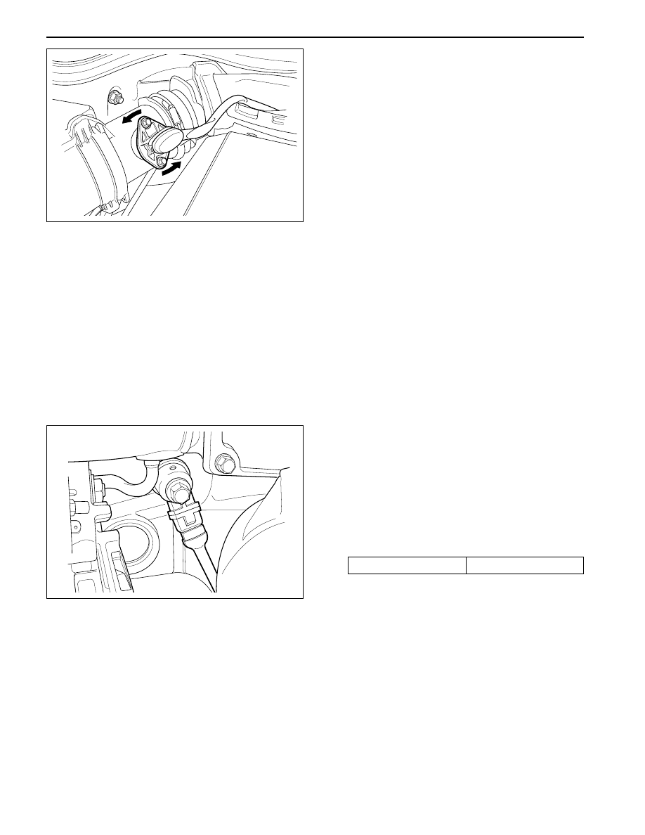
HOT FILM AIR MASS (HFM)
SENSOR

Removal and Installation Procedure

1. Disconnect the negative battery cable.

2. Disconnect the Hot Film Air Mass (HFM) sensor

electrical connector.

3. Remove the HFM sensor retaining screws.

4. Turn the HFM sensor coupling in the direction

shown in the figure in the left so that it gets
separated from the contact surface.

Notice:  Make sure the HFM sensor coupling
connects completely with the contact surface
installation.

5. Remove the HFM sensor.

6. Installation should follow the removal procedure

in the reverse order.

Tightening Torque

25 N•m (18 lb-ft)

4. Remove the knock sensor.

5. Installation should follow the removal procedure

in the reverse order.

M162 ENGINE CONTROLS  1F1-91

SSANGYONG  Y200

KAA1F410

YAD1F640

Important: A special anti-seize compound is used
on the oxygen sensor threads. This compound
consists of a liquid graphite and glass beads. The
graphite will burn away, but the glass beads will
remain, making the sensor easier to remove. New
or serviced sensors will al-ready have the
compound applied to the threads. If a sensor is
removed from any engine and is to be rein-stalled,
the threads must have an anti-seize compound
applied before reinstallation.

4. Coat the threads of the oxygen sensor with an anti-

seize compound, if needed.

5. Installation should follow the removal procedure

in the reverse order.

PEDAL POSITION SENSOR

Removal and installation Procedure

1. Disconnect the negative battery cable.

2. Disconnect the pedal position sensor connector.

3. Unscrew the bolts and nut.

Installation Notice

Tightening Torque

6 N•m (53 lb-ft)

4. Remove the pedal and sensor assembly.

5. Installation should follow the removal procedure

in the reverse order.

OXYGEN SENSOR

Removal and Installation Procedure

1. Disconnect the negative battery cable.

Notice: The oxygen sensor uses a permanently
attached pigtail and connector. This pigtail should
not be removed from the oxygen sensor. Damage
or removal of the pigtail or the connector could
affect proper operation of the oxygen sensor. Do
not drop the oxygen sensor.

2. Disconnect the electrical connector.

3. Carefully remove the oxygen sensor from the

exhaust pipe.

Installation Notice

Tightening Torque

55 N•m (41 lb-ft)

SSANGYONG  Y200

1F1-92  M162 ENGINE CONTROLS

YAD1F650

YAD1F660

YAD1F670

KAA1F170

PURGE CONTROL  VALVE

Removal and Installation Procedure

1. Disconnect the negative battery cable.

2. Disconnect the purge control valve connector.

3. Disconnect the throttle body-to-purge control valve

hose from the purge control valve.

4. Disconnect the canister-to-purge control valve

hose from the purge control valve.

5. Remove the purge control valve.

6. Installation should follow the removal procedure

in the reverse order.

CANISTER

Removal and Installation Procedure

Caution: Canister and vacuum hoses contain fuel
vapors. Do not smoke in the area or permit an open
flame.

1. Disconnect the fuel tank-to-canister hose form the

canister.

2. Disconnect the canister-to-purge control valve

hose form the canister.

Tightening Torque

6 N•m (53 lb-ft)

4. Remove the canister.

5. Installation should follow the removal procedure

in the reverse order.

3. Remove the canister mounting bolts.

Installation Notice

CAMSHAFT POSITION SENSOR

Removal and Installation Procedure

1. Disconnect the negative battery cable.

2. Disconnect the electrical connector from the

camshaft position sensor.

3. Remove the camshaft position sensor retaining

bolt.

Installation Notice

Tightening Torque

10 N•m (89 lb-ft)

M162 ENGINE CONTROLS  1F1-93

SSANGYONG  Y200

KAA1F160

KAA1F200

4. Check the O-ring for damage and replace it if

neces sary.

5. Installation should follow the removal procedure

in the reverse order.

CRANKSHAFT POSITION SENSOR

Removal and installation Procedure

1. Disconnect the negative battery cable.

2. Disconnect the electrical connector at the

crankshaft position sensor.

3. Remove the crankshaft position sensor retaining

bolt.

Installation Notice

Tightening Torque

25 N•m (18 lb-ft)

4. Installation should follow the removal procedure

in the reverse order.

ENGINE CONTROL MODULE

Removal and installation Procedure

1. Disconnect the negative battery cable.

2. Remove the cowl side trim form passenger side.

Refer to Section 9G, Interior trim.

3. Remove the four securing nuts for the Engine

Control Module (ECM) from the mounting bracket.

Installation Notice

4. Pull out the ECM from the bracket.

5. Disconnect the vehicle side coupling.

6. Installation should follow the removal procedure

in the reverse order.

Tightening Torque

25 N•m (18 lb-ft)


Content   ..  416  417  418  419   ..