SsangYong Korando II (1996-2006 year). Manual - part 432


  Index      SsangYong     SsangYong Korando II - service repair manual 1996-2006 year


Search            


Content   ..  430  431  432  433   ..


SsangYong Korando II (1996-2006 year). Manual - part 432


INSTRUMENTATION, DRIVER INFORMATION  9E-9

SSANGYONG  MY2002

INSTRUMENT CLUSTER INDICATOR LAMPS

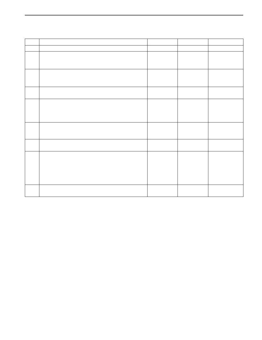
Instrument Cluster Indicator Lamps Do Not Operate

Step

1

2

3

4

5

6

7

8

9

Action

Is fuse F30 blown?
1. Check for a short circuit and repair if necessary.
2. Replace the blown fuse.
Is the relpair complete?
1. Turn the ignition ON.
2. Check the votage at fuse F30.
Does the battery voltage match the value specified?
Repair the open power supply circuit to fuse F30.
Is the repair complete?
1. Remove the instrument cluster.
2. Disconnect the instrument cluster connectors A1.
3. Turn the ignition ON.
Does the battery voltage match the value specified?
Repair the open circuit between fuese F30 and the
instrument cluster connectors A1.
Is the repair complete?
Check the instrument cluster warning lamp bulbs.
Are the bulbs OK?
1. Replace any warning lamp bulbs that were

defective.

2. Check the charging system to make sure the

alternator is not overcharging.

3. Repair the charging system if necessary.
Is the repair complete?
Replace the instrument cluster.
Is the repair complete?

Yes

Go to Step 2

System OK

Go to Step 5

System OK

Go to Step 7

System OK

Go to Step 9

System OK

System OK

No

Go to Step 3

-

Go to Step 4

-

Go to Step 6

-

Go to Step 8

-

-

Value(s)

-

-

11 - 14 v

-

11 - 14 v

-

-

-

-

SSANGYONG  MY2002

9E-10  INSTRUMENTATION, DRIVER INFORMATION

COOL

HOT

KAA9E030

KAA9E040

CENTER FACIA

Removal and Installation Procedure

1. Remove the floor console. Refer to Section 9G,

Floor Console

2. Remove the center tray. Refer to “Center Tray” in

this section.

3. Remove the center facia with the screws.

4. Installation should follow the removal procedure

in the reverse order.

ASHTRAY

Removal and Installation Procedure

1. Remove the center facia. Refer to “Center Facia”

in this section.

2. Remove the ashtray assembly from the center

facia.

3. Installation should follow the removal procedure

in the reverse order.

KAA9E020

ON-VEHICLE SERVICE

UNIT REPAIR

CENTER TRAY

Removal and Installation Procedure

1. Pull the center tray.

2. Installation should follow the removal procedure

in the reverse order.

REPAIR INSTRUCTIONS

INSTRUMENTATION, DRIVER INFORMATION  9E-11

SSANGYONG  MY2002

KAA9E060

KAA9E070

CUP HOLDER

Removal and Installation Procedure

1. Remove the center facia. Refer to “Center Facia”

in this section.

2. Remove the cup holder with the screws.

3. Installation should follow the removal procedure

in the reverse order.

KAA9E050

CIGAR LIGHTER

Removal and Installation Procedure

1. Removed the floor console. Refer to “floor

console” in this section.

2. Remove the center tray. Refer to “Center tray” in

this section.

3. Remove the center facia with the screws. Refer to

“Center Facia” in this section.

4. Remove the ashtray assembly with the screws.

Refer to  “Ashtray” in this section.

5. Disconnect the cigar lighter connector.

6. Turn the cigar lighter locker and remove.

7. Installation should follow the removal procedure

in the reverse order.

INSTRUMENT PANEL VENT

Removal and Installation Procedure

1. Remove the center facia. Refer to “Center Facia”

in this section.

2. Remove the instrument panel vents from the center

facia.

3. Installation should follow the removal procedure

in the reverse order.

SSANGYONG  MY2002

9E-12  INSTRUMENTATION, DRIVER INFORMATION

KAA9E090

KAA9E100

KAA9E110

3. Remove the glove box with the screws

4. Installation should follow the removal procedure

in the reverse order.

HOOD LATCH RELEASE HANDLE

Removal and Installation Procedure

1. Remove the hood latch release handle with the

screws.

2. Installation should follow the removal procedure

in the reverse order.

KAA9E080

GLOVE BOX

Removal and Installation Procedure

1. Remove the side facia panel. Refer to “Side Facia

Panel” in this section.

2. Pull and remove the glove box stopper of both.

CHIME MODULE

Removal and Installation Procedure

1. Disconnect the negative battery cable.

2. Remove the center tray. Refer to “Center tray” in

this section.

3. Remove the center facia. Refer to “Center Facia”

in this section.

4. Remove the cup holder. Refer to “Cup Holder” in

this section.

5. Remove the chime module with the screws

6. Installation should follow the removal procedure

in the reverse order.


Content   ..  430  431  432  433   ..