SsangYong Musso. Manual - part 543


  Index      SsangYong     SsangYong Musso - service repair manual


Search            


Content   ..  541  542  543  544   ..


SsangYong Musso. Manual - part 543


8B-2  SUPPLEMENTAL RESTRAINT SYSTEM(SRS)

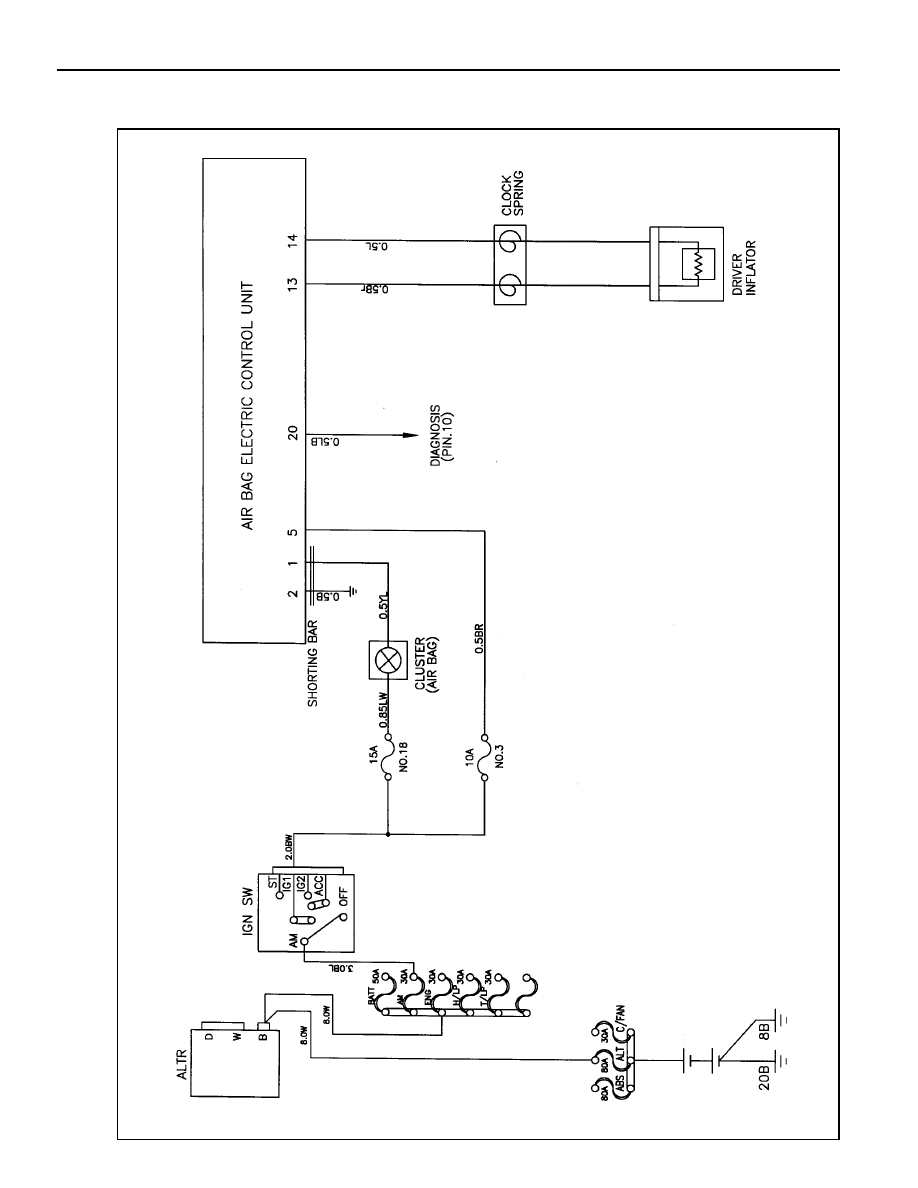
SCHEMATIC  AND ROUTING DIAGRAMS

AIR BAG

SUPPLEMENTAL RESTRAINT SYSTEM(SRS)  8B-3

CAUTIONS

Failure to follow the correct service procedure can cause air bag damage or personal injury due to unexpected air
bag deployment. Before service (removal and installation of part, check for replacement), please be weal noticed of
following items for your correct service.

1. For service, turn the ignition switch to ‘LOCK’ position and wait for 30 seconds after disconnecting the negative

battery cable.

2. If the vehicle collapsed, remove the air bag ECU first to reserve the crash records.

3, Never use other vehicles’ air bag components and replace with specified new part.

4. Never disassemble or repair the air bag module, air bag unit and wiring harness to re-use.

5. Replace the air bag module and air bag unit with new if it dropped, cracked or damaged.

6. Only qualified technicians in service shop should check or repair the air bag,

7. Before service, should be well noticed of warning labels on the vehicle.

A. Sun Visor Side

[Warning]

Pull down the sun visor and see SRS air bag
warning lamp on the head lining.

B. Head Lining

[Warning]

1 . This vehicle is equipped with air bag. Air bag is

supplemental device for the seatbelt. Fasten
your  seatbelt.

2. This air bag should be replaced by authorized

supplier within replacement intervals.

3. When the ignition key is turned to ON position,

SRS warning lamp will turn on for 6 sec. and go
off. In this case, the system is normal.
For the following cases, see service manual.
- SRS warning lamp does not turn on.
- SRS warning lamp does not go off.
- SRS warning lamp continues to blink.

C. Steering Wheel Body Inner

[Warning]

Before removing the steering wheel, read service

manual first. Set the front wheels straight forward

and align the center position marks of SRS clock
spring. Improper removal or installation of the
steering wheel can damage the SRS components.

D. Engine Compartment

[Warning]

This vehicle is equipped with air bag. Before
checking the engine compartment, read service
manual first. Faultuy check and service can cause
SRS air bag deployment and system defects that
can be led to severe damage.

E. Battery Cable

[Warning]

Before disconnecting the battery power, read
service manual first.

8B-4  SUPPLEMENTAL RESTRAINT SYSTEM(SRS)

FUNCTION DESCRIPTION

Air Bag Control Unit (AC4)

Air bag control unit (AC4) is installed on the center portion of
the front floor tunnel.

It is a central control unit that control all functions and determines
whether deploy the air bag or not with the collision signal from
the built-in accelerometer sensor and has function of diagnosing
system defects.

Internal air bag control unit is consisted as follows;

!

Microprocessor

!

ASICs (Upper side ASIC & lower side ASIC)

!

Accelerometer sensor

!

Arming sensor

!

System energy backup condenser

!

Squib energy backup condenser

SUPPLEMENTAL RESTRAINT SYSTEM(SRS)  8B-5

Input & Output Function

Electronic air bag control and diagnosis module is connected
by full 30-pin connectors.

Input : ground

Output : 1 squib line, warning lamp

Input/output : communication, diagnosis

16 Shorting Bar
17 Shorting Bar
18 Shorting Bar
19 Shorting Bar
20 Diagnosis
21 Shorting Bar
22 Shorting Bar
23 No Pin
24 No Pin
25 Shorting Bar
26 Shorting Bar
27 N/A
28 Shorting Bar
29 Shorting Bar
30 N/A

1 Lamp
2 Ground
3 N/A
4 N/A
5 Ignition
6 N/A
7 N/A
8 CONF
9 N/A

10 N/A

11 N/A

12 N/A
13 Squib Line 1(upper)
14 Squib Line 1(lower)
15 N/A

IGN

GND

Warning lamp

RxD/TxD

Inflator line 1

+

-

5

2

1

20

13

14

Air bag lamp

Communication/
diagnosis

Air bag

control

unit

Ground connection or open

Connector Pins

15

30

1

16


Content   ..  541  542  543  544   ..