SsangYong Musso. Manual - part 461


  Index      SsangYong     SsangYong Musso - service repair manual


Search            


Content   ..  459  460  461  462   ..


SsangYong Musso. Manual - part 461


AUTOMATIC TRANSMISSION  5A-21
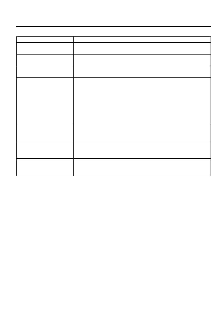
Downshift Type

RANGE ‘1’ (MANUAL ‘1’):

RANGE ‘2’ (MANUAL ‘2’):

RANGE ‘3’ (MANUAL ‘3’):

RANGE ‘D’ (DRIVE):

RANGE ‘N’ (NEUTRAL):

RANGE ‘R’ (REVERSE):

RANGE ‘P’ (PARK):

Inhibited Above

First gear operation only with inhibited engagement as a function of vehicle

speed. Engine braking is applied with reduced throttle.

First and second gear operation with inhibited engagement of second gear, as

a function of vehicle speed. Engine braking is applied with reduced throttle.

First, second and third gear operation with an inhibited third gear engagement

at high vehicle speed. Refer to the vehicle owner’s manual.

Engine braking is applied with reduced throttle.

First, second, third and fourth gear operation. First to second (1-2), first to third

(1-3), second to third (2-3), second to fourth (2-4), third to fourth (3-4), fourth

to third (4-3), fourth to second (4-2), third to second (3-2), third to first (3-1)

and second to first (2-1), shifts are all available as a function of vehicle speed,

throttle position and the time rate of change of the throttle position (forced

downshift). Lockup clutch may be enabled in 3rd and 4th gears depending on

vehicle type. Refer to the owner’s manual.

Rear band applied only, with inhibited engagement as a function of vehicle

speed, engine speed and throttle position. The inhibitor switch allows the en-

gine to start.

Reverse gear operation, with inhibitor engagement as a function of vehicle

speed, engine speed and throttle position. The inhibitor switch enables reverse

lamp operation.

Rear band applied only, with inhibited engagement as a function of vehicle

speed, engine speed and throttle position. The transmission output shaft is

locked. The inhibitor switch allows the engine to start.

Table 2.1 - Gear Selections

DRIVING MODE SELECTOR

The driving mode selector consists of a mode  selection switch and indicator light. The driving mode selector is
located on the centre console. See figure 2,1.

The schedules available to be selected vary with vehicle types. Typically the driver should have the option to select
between ‘NORMAL’ , ‘POWER’ or ‘WINTER’ modes.

When ‘NORMAL’ mode is selected upshifts will occur to maximise fuel economy and the indicator lights remain
extinguished. When ‘POWER’ mode is selected upshifts will occur to give maximum performance and the ‘POWER’
mode indicator light is switched on. When ‘WINTER’ mode is selected, starting at second gear is facilitated, the
‘WINTER’ mode indicator light is switched on and the ‘POWER’ mode indicator light is switched off.

Refer to the vehicle owner’s manual for specific modes for each vehicle type.

5A-22  AUTOMATIC TRANSMISSION

CONTROL SYSTEMS

GENERAL

There are two control systems associated with the transmission. The electronic control system monitors vehicle
parameters and adjusts the transmission performance. The hydraulic control system implements the electronic control
system commands.

ELECTRONIC CONTROL SYSTEM

The electronic control system is comprised of sensors, a TCU and seven solenoids. The TCU reads the inputs, and
under software control activates the outputs according to values stored in read only memory (ROM).

The TCU controls the hydraulic control system. This control is via the hydraulic valve body, which contains seven
electro-magnetic solenoids. Six of the seven solenoids are used to control the line pressure, operate the shift valves
and the torque converter lock-up clutch, and to turn on and off the two regulator valves (The two regulator valves
control the shift feel.).

The seventh solenoid is the proportional or variable pressure solenoid (VPS) which works with the two regulator
valves to control shift feel.

Figure 3.1 details a typical TCU control system schematic.

The individual component locations, operation and specifications which make up the electronic control subsystem
are covered in this section.

Figure 3.1 - Typical TCU Control System Schematic

AUTOMATIC TRANSMISSION  5A-23

Temperature (

°°°°°

C)

-20

0

20

100

135 (Overheat Mode Threshold)

Maximum

17,287

6,616

2,723

196

85

Minimum

13,638

5,177

2,278

177

75

Resistance (Ohms)

Table 3.1 - Temperature / Resistance Characteristics

Figure 3.2 - Temperature / Resistance Characteristics

5A-24  AUTOMATIC TRANSMISSION

Transmission Control Unit(TCU)

The TCU is an in-vehicle micro-processor based transmission management system. It is usually mounted in the
vehicle cabin, under the instrument panel, under the seat, behind the side kick panels or under the floor in the
footwell on the passenger side. Different control units are supplied for different vehicle applications.

The TCU contains:

!

Processing logic circuits which include a central microcontroller and a back-up memory system.

!

Input circuits.

!

Output circuits which control external devices such as the variable pressure solenoid (VPS), on/off solenoid
drivers, a diagnostics output and the driving mode indicator light.

The various items which make up the TCU are discussed below.

Processing Logic

Shift schedule and calibration information is stored in an erasable programmable read only memory (EEPROM).
Throttle input calibration constants and the diagnostics information are stored in electrically erasable programmable
read only memory (EEPROM) that retains the memory even when power to the TCU is disconnected.

In operation the software continuously monitors the input values and uses these, via the shift schedule, to determine
the required gear state, At the same time it monitors, via the solenoid outputs, the current gear state. Whenever the
input conditions change such that the required gear state is different to the current gear state, the TCU initiates a
gear shift to bring the two states back into line.

Once the TCU has determined the type of gear shift required the software accesses the shift logic, estimates the
engine torque output, adjusts the variable pressure solenoid ramp pressure then executes the shift.

The TCU continuously monitors every input and output circuit for short or open circuits and operating range. When
a failure or abnormal operation is detected the TCU records the condition code in the diagnostics memory and
implements a limp mode, The actual limp mode used depends upon the failure detected with the object to maintain
maximum driveability without damaging the transmission. In general input failures are handled by providing a default
value. Output failures, which are capable of damaging the transmission, result in full limp mode giving only third or
fourth gear and reverse. For further details of limp modes and memory retention refer to the Diagnostic Section.

The TCU is designed to operate at ambient temperatures between -40 and 85°C . It is also protected against
electrical noise and voltage spikes, however all the usual precautions should be observed, for example when arc
welding or jump starting.

TCU Inputs

To function correctly, the TCU requires engine speed, road speed, transmission sump temperature, throttle position
and gear position inputs to determine the variable pressure solenoid current ramp and on/off solenoid states. This
ensures the correct gear selection and shift feel for all driving conditions.

The inputs required by the TCU are as follows:

!

Engine Speed

The engine speed signal is derived from the tachometer signal line, a dedicated sensor or a Controlled Area
Network (CAN).

!

Road Speed

4WD (Diesel) - The shaft speed signal is derived from the speedo sensor located on the transfer case. This signal
is transmitted directly to the TCU.

4WD (Gasoline) - The speedo sensor sends the shaft speed signal to the engine control module (ECM). The
information is then transferred to the TCU via the CAN.

!

Transmission Sump Temperature

The transmission sump temperature sensor is a thermistor located in the solenoid wiring loom within the transmission.
This sensor is a typical NTC resistor with low temperatures producing a high resistance and high temperatures


Content   ..  459  460  461  462   ..