SsangYong Musso. Manual - part 416


  Index      SsangYong     SsangYong Musso - service repair manual


Search            


Content   ..  414  415  416  417   ..


SsangYong Musso. Manual - part 416


1F3-14  OM600 ENGINE CONTROLS

Removal & Installation Procedure

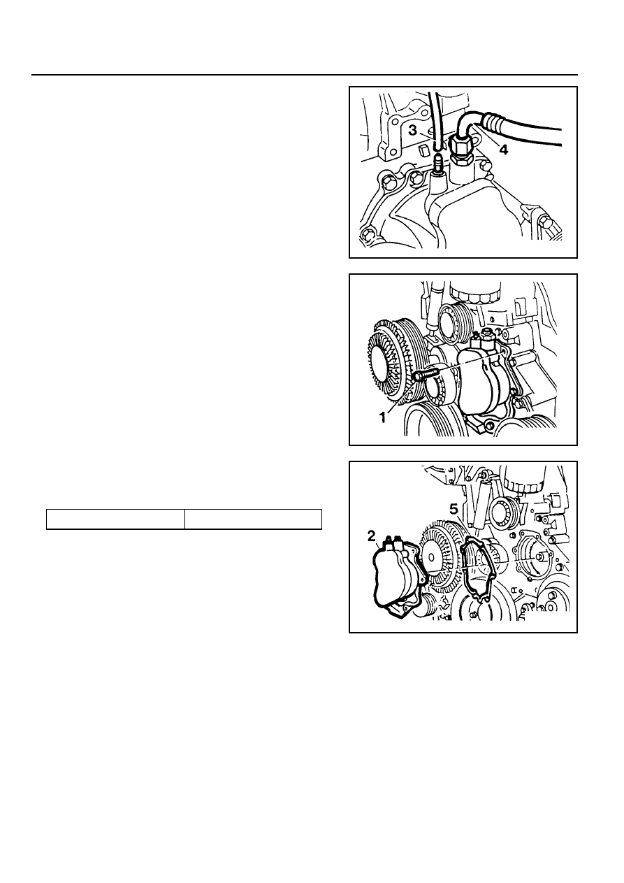
1. Remove the vacuum line (3, 4).

2. Remove the bolts (1) evenly.

Notice

If necessary, rotate the engine until the pressure on the
tappet of the vacuum pump is released.

3. Remove the vacuum pump (2).

4. Install the vacuum pump (2).

Tightening Torque

10 Nm

Notice

Clean the gasket residues of sealing surface of vacuum
pump and replace the gasket(5).

5. Connect the vacuum line (3, 4).

OM600 ENGINE CONTROLS  1F3-15

VACUUM UNIT REPLACEMENT

1 Bracket
2 Bolt
3 Vacuum Unit
4 Vacuum Line
5 Seal .............................................. Replace

1F3-16  OM600 ENGINE CONTROLS

Idle Speed

750 - 850 rpm

720 - 820 rpm

Engine

OM661LA Engine

OM662LA Engine

Tools Required

667 589 00 21 00  TDC Pulse Generato

Commercial Tool

IDLE SPEED ADJUSTMENT

Service Data

e.g. Bosch, MOT 001.03

Sun, DIT 9000

Digital Tester

Adjustment Procedure

1. Connect the digital tester (1) and TDC pulse sender unit

(11).

2. Run the engine and warm up the coolant to 60~80°C.

TDC pulse generator 667 589 02 21 00

3. Disconnect the vacuum hose (4) from the PLA unit to check

idle speed with tester.

4. Check idle speed with tester.

Notice

To adjust idle speed, loosen the locking nut (6) of PLA unit.

OM 661LA Engine

750 - 850rpm

OM 662LA Engine

720 - 820rpm

OM600 ENGINE CONTROLS  1F3-17

6. After adjustment, tighten the locking nut and place the

position marking with different color of paint.

Notice

If there are no changes in idle speed with PLA unit
adjustment, perform the service at a BOSCH Service Center.

7. Connect the vacuum pump to the PLA vacuum unit and

build up vacuum approx. 500mbar. If engine rpm increases
by approx. 100rpm, It is normal.

Vacuum Pump 001 589 73 21 00

8. Connect the vacuum line (4).

9. Switch on all ancillaries and check the idle speed.

5. Ensure not to damage the idle spring in the governor and

adjust idle speed by turning the PLA unit (5) slowly.

Notice

Do not rotate the PLA unit over ½ turn from the position
marking. If do, idle spring in the governor will be severely
damaged.

Clockwise

Counterclockwise

RPM Decrease

RPM Increase


Content   ..  414  415  416  417   ..