SsangYong Musso. Manual - part 368


  Index      SsangYong     SsangYong Musso - service repair manual


Search            


Content   ..  366  367  368  369   ..


SsangYong Musso. Manual - part 368


1B3-34  OM600 ENGINE MECHANICAL

8. Remeasure size ‘X’ and compare it with the first

measurement and determine the thickness of spacer ring.

Size before machining

25.7 mm

Size after machining

    25.5 mm

Ex

The spacer ring should be selected so that it is at least
0.1mm and not more than 0.3mm thicker than the
measured on the sealing surface. In this example, the
necessary thickness of spacer ring should be within
0.3 ~ 0.5mm and the thickness of spacer ring to be
installed is 0.3mm.

9. Remove the countersink tool and clean the chips.

Notice

If the sealing surface is not completely flat, remachine the
sealing surface.

10. emove rag from the prechamber bore and crank the engine

with starter motor to threw out any chips which may have
got into the combustion chamber.

11. Insert the proper spacer ring into the prechamber sealing

surface.

12. Punch a mark on the cylinder head above the prechamber

sealing surface which has been machined.

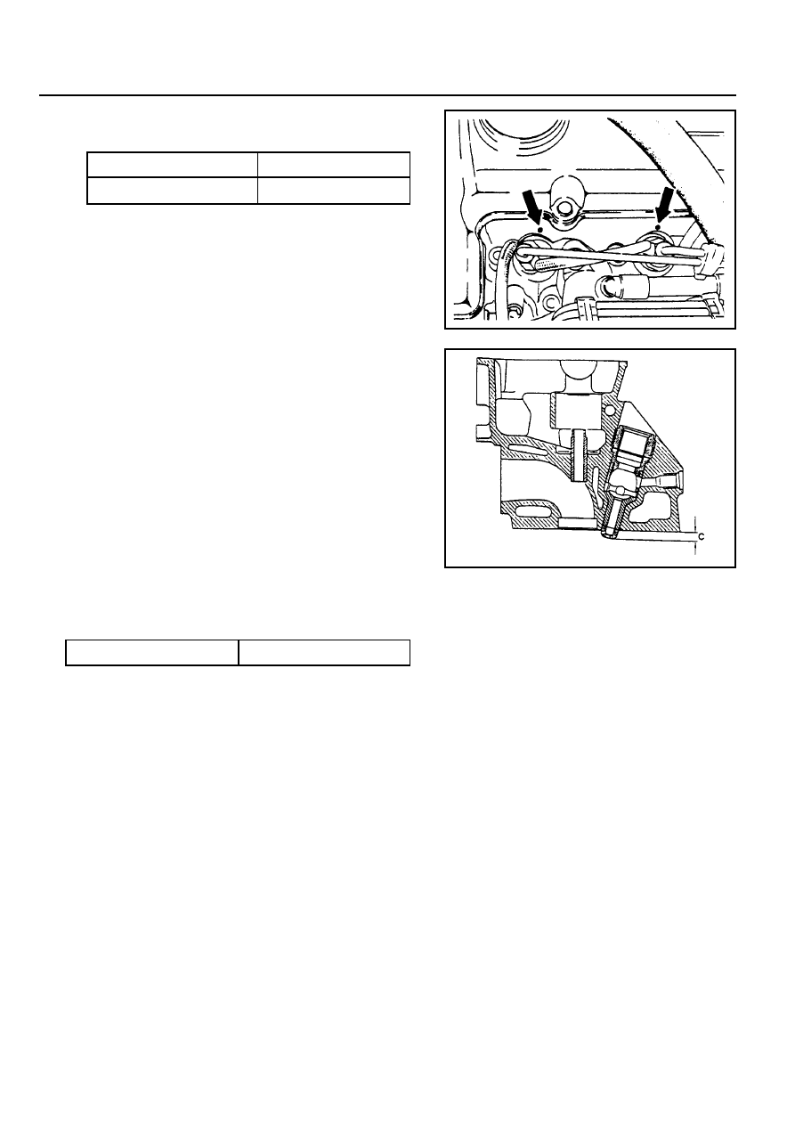
13. Install the prechambers.

Notice

If the cylinder head is removed, the projection ‘C’ is
measured in place of size ‘X’ and the appropriate size of
spacer ring selected.

Normal Projection (c)

7.6 - 8.1mm

OM600 ENGINE MECHANICAL  1B3-35

TDC (TDC SENSOR BRACKET) SETTING

Preceding Work : Removal of No.1 cylinder prechamber

1 Measuring Device
2 Dial Gauge
3 Cylinder Head
4 Piston ................................................ Set at TDC

Tools Service

001 589 32 21 00  Dial Gauge

601 589 07 21 00  Deqth Gauge

667 589 01 21 00  Fixing Device

Notice

!

The TDC sensor bracket must be adjusted in case of
followings.

!

When replacing the TDC sensor bracket.

!

When replacing the crankshaft, the hub or the vibration
damper.

!

When replacing or installing the timing case cover.

!

After engine overhauling.

If the cylinder head is removed, the measuring pin of the
dial gauge can be positioned on the piston crown.

This is done by placing the magnetic dial holder on the
mating surface of the crankcase.

1B3-36  OM600 ENGINE MECHANICAL

Setting (with cylinder head installed)

1. Remove the prechamber of No. 1 cylinder.

2. Position the piston of No.1 cylinder at BTDC 10.

3. Install the measuring device into the prechamber bore and

position the dial gauge with a preload of 5mm.

Dial Gauge 001 589 53 21 00

Depth Gauge 601 589 07 21 00

4. Slowly rotate the crankshaft in the direction of engine rotation

until the large pointer on the dial gauge stops (TDC position).

Notice

The position of TDC is when the large pointer on the dial
gauge is stopped before moving back.

5. remove the reinstall the measuring device and position the

dial gauge scale at ‘0’.

6. Slowly rotate the crankshaft in the direction of engine rotation

until the dial gauge has moved back (counterclockwise) by
3.65mm.

7. Insert fixing device into the sensor bracket.

Notice

The pin on the vibration damper must engage into the slot
of the fixing device.

Fixing Device 667 589 01 21 00

8. If the pin does not engage, adjust the setting of the sensor

bracket by removing and tightening of the sensor bracket
bolts.

Tightening Torque

10 Nm

Notice

The timing mark on the damper must be positioned at ATDC
20.

OM600 ENGINE MECHANICAL  1B3-37

CYLINDER HEAD

1 Fuel Injection Pipe ..................................... 18Nm
2 Cylinder Head
3 Gasket ................................................... Replace
4 Bolt ............................................................ 25Nm
5 Washer
6 Clamp
7 Heater Feed Pipe
8 Bolt
9 Washer

10 Bolt

11 Nozzle Washer ....................................... Replace

12 Fuel Injection Nozzle ............................ 35-40 Nm
13 Hexagon Socket Bolt ................................. 25 Nm
14 Washer
15 Bolt ........................................................... 25 Nm
16 Cylinder Head Bolt .............................. See Table
17 Cylinder Head Cover
18 Bolt ........................................................... 10 Nm
19 Gasket
20 Camshaft

21 Camshaft Drive Sprocket ....................... Replace
22 Washer
23 Bolt(12-Sided) .................................. 25Nm + 90°
24 Sliding Rail
25 Sliding Rail Pin
26 Sliding Rail Pin
27 Chain Tensioner ....................................... 80 Nm
28 Gasket ................................................... Replace
29 Cooling Fan .............................................. Check
30 Hexagon Socket Bolt ................................. 45 Nm
31 Tensioning Lever
32 Bolt ........................................................... 25 Nm
33 Bolt
34 Nut ............................................................ 23 Nm
35 Fuel Filter
36 Turbo Charger
37 Intake Duct
38 Gasket ................................................... Replace
39 Intake Manifold


Content   ..  366  367  368  369   ..