SsangYong Musso. Manual - part 359


  Index      SsangYong     SsangYong Musso - service repair manual


Search            


Content   ..  357  358  359  360   ..


SsangYong Musso. Manual - part 359


GENERAL ENGINE INFORMATION  1A3-13

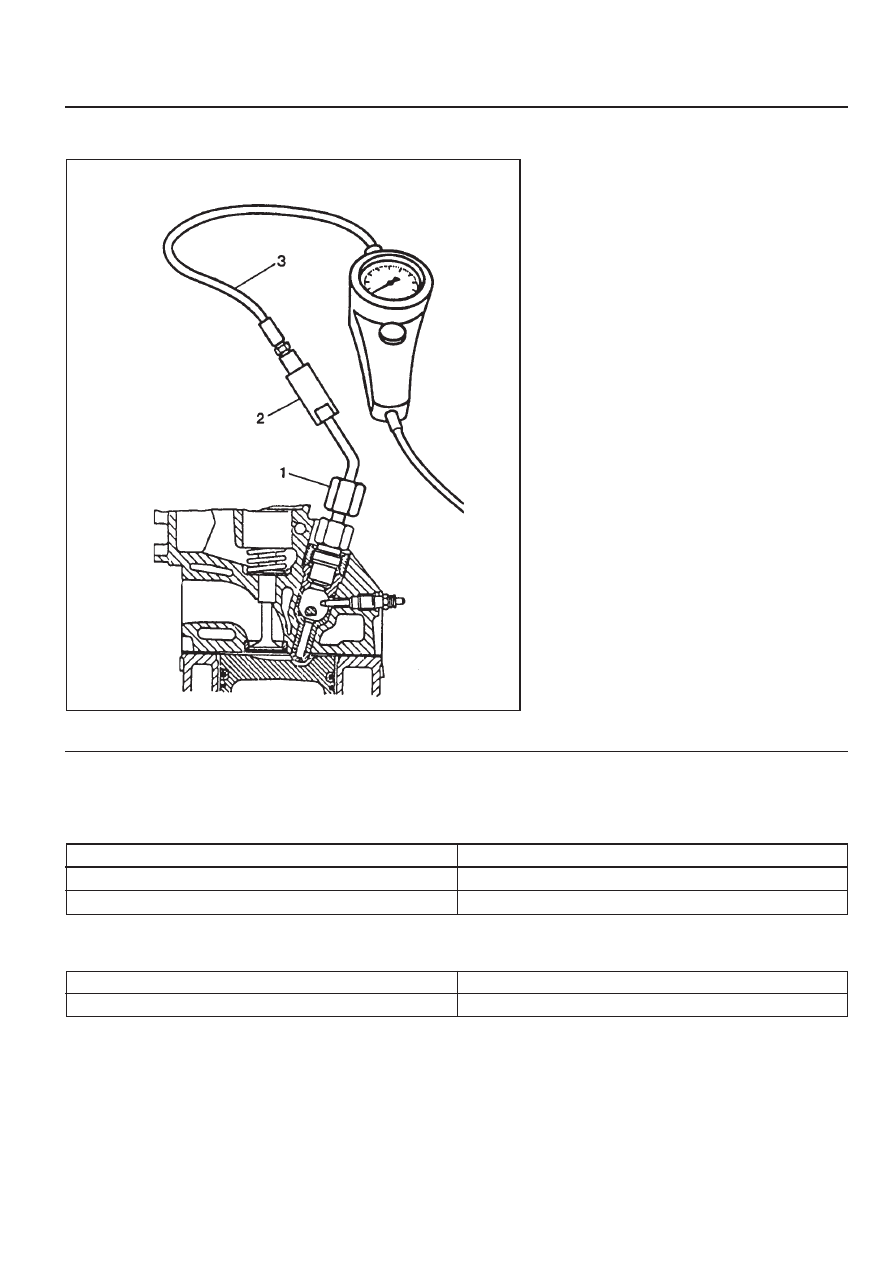
Cylinder Pressure Leakage tester

Connection Piece

CYLINDER PRESSURE LEAKAGE TEST

1 Connector
2 Connection Piece
3 Connection Hose

Permissible Pressure Leakage (Engine at Normal Operating Temperature of 80°C)

At Whole Engine

At Valve and Cylinder Head Gasket

At Piston and Piston Ring

Max. 25 %

Max. 10 %

Max. 20 %

Commercial Tools

BOSCH, EFAW 210 A or SUN CLT 228

BOSCH order no. 1 687 010 016

1A3-14  GENERAL ENGINE INFORMATION

Leakage Test

1. Run the engine to be the coolant temperature 80°C.

2. Remove the fuel injection nozzle.

3. Open the coolant subtank  cap.

4. Check the coolant level and replenish if necessary.

5. Open the oil filler cap.

6. Remove the air cleaner cover and element.

7. Position the piston  at TDC.

8. Install the connector (1) and connection piece (2).

9. Calibrate the tester and connect the connection hose

(3)

10. Pressurize with compressed air and compare the

pressure changes with permissible pressure leakage.

11. If permissible pressure leakage is out of standard, check

followings :

- Intake and exhaust lines.

- Sounds in oil filler area.

- Air bubbles in radiator coolant.

12. Do pressure leakage test for the remaining cylinders

according to the firing order.

z

OM 662LA Engine : 1-2-4-5-3

z

OM 661LA Engine : 1-3-4-2

13. Remove the tester.

14. Close the coolant pressure cap and oil filler cap.

15. Install the air cleaner element and cover.

16. Install the fuel injection nozzle.

GENERAL ENGINE INFORMATION  1A3-15

GENERAL INFORMATION

CLEANLINESS AND CARE

An automobile engine is a combination of many
machined, honed, polished and lapped surfaces with
tolerances that are measured in the ten-thousanths
of an inch. When any internal engine parts are
serviced, care and cleanliness are important. A liberal
coating of enigne oil should be applied to friction areas
during assembly, to protect and lubricate the surfaces
on initial operation. Proper cleaning and protection
of machined surfaces and friction areas is part fo the
repair procedure. This is considered standard shop
practice even if not specifically stated.

Whenever valve train components are removed for
service, they should be kept in order. They should be
installed in the same locations, and with the same
mating surfaces, as when they were removed.

Battery cables should be disconnected before any
major work is performed on the engine. Failure to
disconnect cables may result in damage to wire
harness or other electrical parts.

ON-ENGINE SERVICE

Caution: Disconnect the negative battery cable
before removing or installing any electrical unit,
or when a tool or equipment could easily come in
contact with exposed electrical terminals.
Disconnecting this cable will help prevent
personal injury and damage to the vehicle. The
ignition must also be in LOCK unless otherwise
noted.

Notice: Any time the air cleaner is removed, the intake
opening should be covered. This will protect against
accidental entrance of foreign material, which could
follow the intake passage into the cylinder and cause
extensive damage when the engine is started.

SECTION 1B3

OM600 ENGINE MECHANICAL

CAUTION: Disconnect the negative battery cable before removing or installing any electrical unit or when a
tool or equipment could easily come in contact with exposed electrical terminals. Disconnecting this cable
will help prevent personal injury and damage to the vehicle. The ignition must also be in LOCK unless otherwise
noted.

Specifications . . . . . . . . . . . . . . . . . . . . . . .  1B3-2

Fastener  Tightening  Specifications . . . . . . . .  1B3-2

Special  Tools . . . . . . . . . . . . . . . . . . . . . . .  1B3-4

Special Tools Table . . . . . . . . . . . . . . . . . . . .  1B3-4

Maintenance and Repair . . . . . . . . . . . . .  1B3-12

On-Vehicle Service . . . . . . . . . . . . . . . . . . . .  1B3-12

Engine Assembly . . . . . . . . . . . . . . . . . . . .  1B3-12

Poly V-Belt . . . . . . . . . . . . . . . . . . . . . . . . .  1B3-21

Tensioning Device. . . . . . . . . . . . . . . . . . . .  1B3-23

Poly V-Belt Alignment & Inspection . . . . . . .  1B3-26

Prechamber . . . . . . . . . . . . . . . . . . . . . . . .  1B3-29

Milling of Prechamber Sealing Surface . . . .  1B3-32

TDC (TDC Sensor Bracket) Setting . . . . . .  1B3-35

Cylinder Head . . . . . . . . . . . . . . . . . . . . . . .  1B3-37

Timing Case Cover . . . . . . . . . . . . . . . . . . .  1B3-63

Crankshaft End Cover . . . . . . . . . . . . . . . .  1B3-71

Vibration Damper and Hub . . . . . . . . . . . . .  1B3-74

Crankshaft Front Radial Seal . . . . . . . . . . .  1B3-80

Crankshaft Ball Bearing . . . . . . . . . . . . . . .  1B3-82

Crankshaft . . . . . . . . . . . . . . . . . . . . . . . . .  1B3-83

Flywheel . . . . . . . . . . . . . . . . . . . . . . . . . . .  1B3-93

Machining of Flywheel . . . . . . . . . . . . . . . .  1B3-97

Flywheel Ring Gear . . . . . . . . . . . . . . . . . .  1B3-98

Hydraulic Valve Clearance Compensation
  Element Check . . . . . . . . . . . . . . . . . . . .  1B3-101

Valve Tappets . . . . . . . . . . . . . . . . . . . . . .  1B3-103

Valve Spring Check . . . . . . . . . . . . . . . . .  1B3-105

Valve Springs (Cylinder Head Removed) .  1B3-106

TABLE OF CONTENTS

Valve Springs (Cylinder Head Installed) . .  1B3-109

Valve Stem Seals . . . . . . . . . . . . . . . . . . .  1B3-112

Check and Replacement of

Valve Guides . . . . . . . . . . . . . . . . . . . . .  1B3-116

Valve Seat Rings . . . . . . . . . . . . . . . . . . .  1B3-122

Check and Machining of Valves . . . . . . . .  1B3-127

Machining of Valve Seat . . . . . . . . . . . . . .  1B3-132

Camshaft Timing Test . . . . . . . . . . . . . . . .  1B3-137

Camshaft . . . . . . . . . . . . . . . . . . . . . . . . .  1B3-139

Chain  Tensioner . . . . . . . . . . . . . . . . . . . .  1B3-145

Timing Chain. . . . . . . . . . . . . . . . . . . . . . .  1B3-147

Tensioning Rail . . . . . . . . . . . . . . . . . . . . .  1B3-151

Cylinder Head Guide Rail . . . . . . . . . . . . .  1B3-152

Timing Case Cover Guide Rail . . . . . . . . .  1B3-156

Crankshaft  Sprocket . . . . . . . . . . . . . . . . .  1B3-158

Piston . . . . . . . . . . . . . . . . . . . . . . . . . . . .  1B3-163

Oil Filter . . . . . . . . . . . . . . . . . . . . . . . . . .  1B3-169

Oil Pan . . . . . . . . . . . . . . . . . . . . . . . . . . .  1B3-171

Oil Spray Nozzle . . . . . . . . . . . . . . . . . . . .  1B3-174

Oil Pump . . . . . . . . . . . . . . . . . . . . . . . . . .  1B3-175

Unit Repair . . . . . . . . . . . . . . . . . . . . . . .  1B3-177

Cylinder Head Pressure Leakage Test . . .  1B3-177

Facing Cylinder Head Mating Surface. . . .  1B3-178

Replacement of Crankcase Core Plug . . .  1B3-180

Facing Crankcase Contacting Surface . . .  1B3-182

Oil Gallery Steel Ball . . . . . . . . . . . . . . . . .  1B3-183

Cylinder Bore Measurement . . . . . . . . . . .  1B3-187


Content   ..  357  358  359  360   ..