SsangYong Musso. Manual - part 324


  Index      SsangYong     SsangYong Musso - service repair manual


Search            


Content   ..  322  323  324  325   ..


SsangYong Musso. Manual - part 324


1F1-54  M162 ENGINE CONTROLS
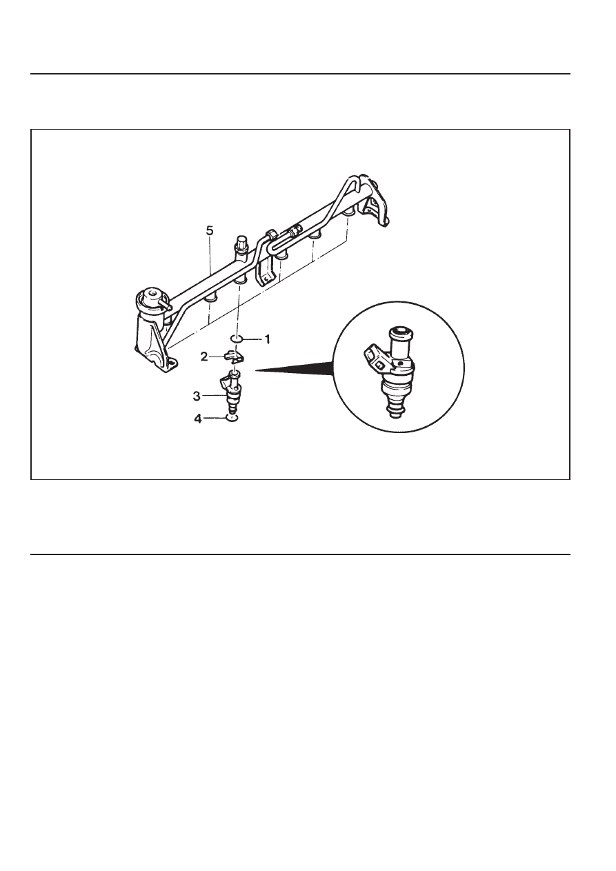
INJECTOR

Preceding Work : Removal of fuel distributor

1 O-ring .................................... rplace, if damaged
2 Injector Bracket
3 Injector

4 O-ring .................................. replace, if damaged
5 Fuel Distributor

M162 ENGINE CONTROLS  1F1-55

Removal & Installation Procedure

1. Remove the O-ring.

Check for damage and replace it if necessary.

2. Remove the injector bracket from the injector.

Installation Notice

Exactly seat the anti-twist lock into the square groove in
injector.

3. Separate the injector from the fuel distributor.

Inspection & Maintenance

Inspection of the Injector operation and spray pattern

1. Connect the contact box to the ECU.

2. Connect the shop made test plug to the injector and place

it into the tank.

3. Position the ignition switch to ON.

4. Connect the pin 63(+) and 69(-) of the contact box with a

test cable.

5. Check the injector spray pattern.

Notice

Replace the injector if the injector spray pattern is abnormal
or the fuel doesn't inject.

Injector Resistance Inspection

1. Remove the injector connector.

2. Measure the injector coil resistance using a resistance

tester.

Notice

Replace the injector if the measured values is out of the
specified values. Check the connector and wire connection
between the ECU and the injector if the measured values
are normal.

Specified Value

14 - 17 

1F1-56  M162 ENGINE CONTROLS

The Injector Spray Pattern Check

1. Connect the test box (129 589 00 21 00) to the ECU.

2. Disconnect the connector from connector.

3. Disconnect the fuel distributor and injector with a unit from

engine without removing the fuel supply and return line.

Notice

Prepare the beaker for taking the poping fuel.

4. Connect either end of shop made cable to the injector.

5. Connect the other end of shop made cable to the No.21

(+:63)and No.3(-:69) terminal of the test box.

6. Turn the ignition switch to "ON" position.

7. Check the injector for normal spray pattern as shown in the

figure. Check injector for leaks or later drops.

Notice

Refer to fuel injector test of engine diagnosis in this section
for detailed information.

M162 ENGINE CONTROLS  1F1-57

FUEL FILTER

1 Fuel Filter
2 Outlet

Removal & Installation Procedure

1. Open the fuel tank cap and remove the fuel tank pressure.

2. Remove the fuel at (2) and in (3).

Installation Notice

Notice

Place the fuel pump pad. There may be a corrosion due to
the contact between the fuel filter and the bracket.

4. Check for leaks by operating the engine.

Notice

Installation should follow the removal procedure in the
reverse order.

3. Remove the mounting bracket bolt (4) and remove the fuel

filter (1).

Installation Notice

3 Inlet

Tightening Torque

25 - 30 Nm

Tightening Torque

4 - 8 Nm


Content   ..  322  323  324  325   ..