SsangYong Musso. Manual - part 319


  Index      SsangYong     SsangYong Musso - service repair manual


Search            


Content   ..  317  318  319  320   ..


SsangYong Musso. Manual - part 319


1F1-34  M162 ENGINE CONTROLS

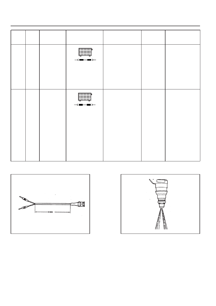
Figure 9. Shop Made Cable

Figure 10. Fuel Injector Normal Spary Pattern

Failure

code

Item

Checking method

Test

step

Requirement

Specified

value

Possible cause

There should

be no leaks

and later

drops from

the injector

•••••

 Injector:

- Leakage test

 Ignition:ON

- Remove the fuel

distributor and fuel

injector with a unit.

⇒ 

1.0

The spray

pattern of the

injector most

show in the

figure 10.

 Ignition:ON

- Connect the shop

made cable to the

injector

- Collect the spraying

fuel with a beaker

- Connect the shop

made cable to

No.21(+) and No.3

  (-) terminal in test

box

⇒ 

2.0

 Injector

5

33

•••••

 Injector:

- Function test

and spray

pattern

check

5

33

M162 ENGINE CONTROLS  1F1-35

MAINTENANCE AND REPAIR

ON-VEHICLE SERVICE

ECU

Appearance

1 Cover
2 Plate
3 Connector
4 Flat Pin

Vehicle Side : No. 1 - 12
Engine Side : No. 61 - 72

5 Pin

Vehicle Side : No. 13 - 60
Engine Side : No. 73 - 120

A Vehicle Side Connector : Black
B Engine Side Connector : Gray

1F1-36  M162 ENGINE CONTROLS

Location

Engine ECU is located at the inside of cowl side trim in right
bottom of instrument panel of passenger side.

Removal & Installation Procedure

1. Turn the ignition switch to "OFF" position.

2. Disconnect the battery negative cable

3. Remove the cowl side trim form passenger side.

4. Unscrew four securing nuts for ECU from mounting bracket.

Installation Notice

5. Pulling out the ECU from bracket.

6. Disconnect the vehicle side coupling(B).

7. Installation should follow the removal procedure in the

reverse order.

Tightening  Torque

9 - 11 Nm

M162 ENGINE CONTROLS  1F1-37

Pin No.

Abbreciation

Description

1

2

3

4

5

6

7

8

9

10

11

12

13

14

15

16

17

18

19

20

-

TM.50

-

-

GND

-

-

-

LSH1

TM.31

TM.87

TM.30

WFS I/O

WFS O

-

GND

LS1

-

-

-

-

Starter motor TM.50

-

-

Electronic ground

-

-

-

Lambda probe 1 heating

Power ground TM.31

V-BATTERY TM.87

V-BATTERY TM.30

Immobilizer crypto read

Immobilizer crypto write

-

Lambda probe 1 ground

Lambda probe 1 signal

-

-

-

ECU Pin Numbers and Descriptions

Vehicle Connector


Content   ..  317  318  319  320   ..