SsangYong Musso. Manual - part 256


  Index      SsangYong     SsangYong Musso - service repair manual


Search            


Content   ..  254  255  256  257   ..


SsangYong Musso. Manual - part 256


M162 ENGINE MECHANICAL  1B1-67
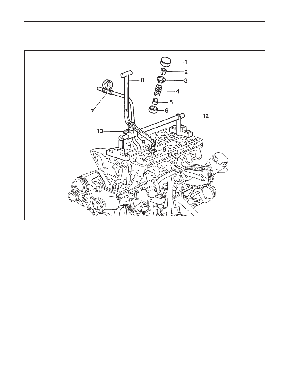
VALVE SPRING

Preceding Work : Removal of camshaft

Removal of spark plug

1 Valve Tappet Assembly
2 Valve Cotter
3 Upper Retainer
4 Valve Spring .......... Check, Replace if necessary
5 Valve Stem Seal
6 Lower Retainer

7 Connecting Hose
8 Thrust Piece
9 Slide

10 Adjust Bolt

11 Lever Pusher

12 Supporting Bar

1B1-68  M162 ENGINE MECHANICAL

Tools Required

111 589 01 59 00

Supporting Bar

111 589 18 61 00

Lever Pusher

111 589 25 63 00

Thrust Piece

116 589 06 63 00 Magnetic Finger

Removal & Installation Procedure

1. Place the supporting bar (12) and the slide (9) at the

camshaft bearing cap (Nos 1 & 7/8&14) and tighten them
with the bearing cap bolt.

Installation Notice

2. Turn the crankshaft to position the each cylinder piston at

TDC.

5. Install the engine lock to the ring gear to prevent the

crankshaft from rotating.

6. Blow up with compressed air.

Notice

z

Remove the valve spring only at TDC.

z

Always rotate the crankshaft by holding the chain to
prevent from timing chain damage and tangling, and for
smooth rotation.

3. Remove the valve tappet (1) using the magnetic finger.

4. Install the leakage tester connecting hose to the spark plug

hole.

Supporting  Bar  111  589  01  59  00

Tightening Torque

22.5 - 27.5 Nm

Mark on The Vibration Damper

OT

120°

240°

Cylinder

1, 6

2, 5

3, 4

M162 ENGINE MECHANICAL  1B1-69

8. Install the lever pusher (11) and the thrust piece (8) to the

slide (9).

13. Remove the valve cotter (2) using either the pincette (13)

or magnetic finger.

Lever  Pusher  111  589  18  61  00

Magnetic  Finger  116  589  06  63  00

9. Mount the thrust piece (8) vertically to the valve spring

retainer (3).

10. Make the thrust piece (8) and the slide (9) perpendicular

to each other.

11. Secure the slide (9) by turning the adjust bolt (10).

12. Press the valve spring (4) by using the lever pusher (11).

14. Remove the upper retainer (3) and the valve spring (4).

15. Remove the valve stem seal and replace if necessary.

Notice

Check the valve stem seal and replace if necessary.

16. Remove the lower retainer (6).

Notice

Check the retainer for damages and replace with a new
one if necessary.

17. Installation should follow the removal procedure in the

reverse order.

1B1-70  M162 ENGINE MECHANICAL

Test (Upper and Lower Valve Tappet and Valve
Cotter)

z

Upper Valve Spring Retainer

z

Lower Valve Spring Retainer

z

Valve Cotter

12.3

 (D)

(d)

 8.5

 Size (mm)

Thickness (mm)

 (a)

0.8 - 1.0

9.2 - 9.8

 (H)

(B)

9.0

 Size (mm)


Content   ..  254  255  256  257   ..